
Antenna/beam selection training in MIMO wireless LANS with different sounding frames

一种无线局域、天线选择的技术,应用在无线通信、无线电传输系统、网络拓扑等方向

Inactive Publication Date: 2008-11-12
MITSUBISHI ELECTRIC RES LAB INC
View PDF1 Cites 21 Cited by
  • Summary
  • Abstract
  • Description
  • Claims
  • Application Information

AI Technical Summary

Problems solved by technology

thus introducing an overhead in the existing training frame design

Method used


Image

  • Antenna/beam selection training in MIMO wireless LANS with different sounding frames
  • Antenna/beam selection training in MIMO wireless LANS with different sounding frames
  • Antenna/beam selection training in MIMO wireless LANS with different sounding frames

Examples


Embodiment Construction

[0052] The present invention provides a training method for antenna / beam selection in a MIMO wireless local area network (WLAN). This method operates at the MAC layer. Compared to prior art antenna / beam selection training methods, the method according to the present invention does not require modification of the PHY layer.

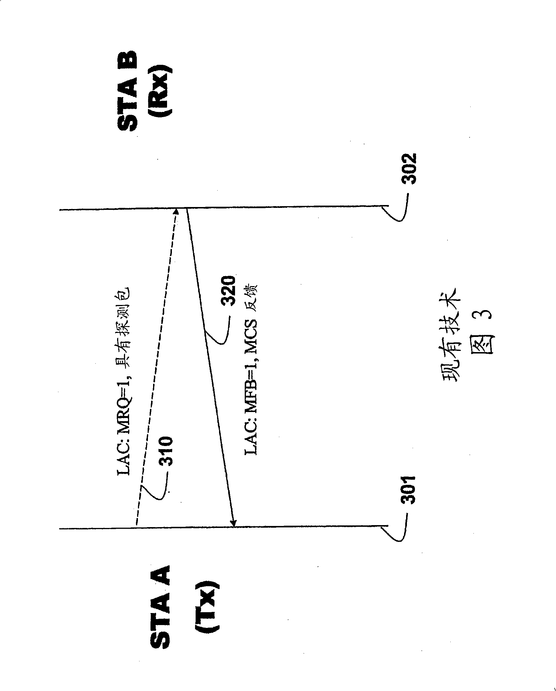
[0053] This training method rapidly sends multiple training frames called probe packets. Each sounding frame is consistent with conventional PHY layer design and is used for a different subset of all available antennas, enabling the receiver of the sounding packet to estimate the characteristics of the entire channel. The receiver of the sounding packet can select either the transmit antenna or the receive antenna. The entire training method operates at the MAC layer.

[0054] In addition to estimating the MIMO channel for antenna / beam selection, the sounding packets can also include data making this method extremely efficient since estimation and data ...


PUM


Abstract

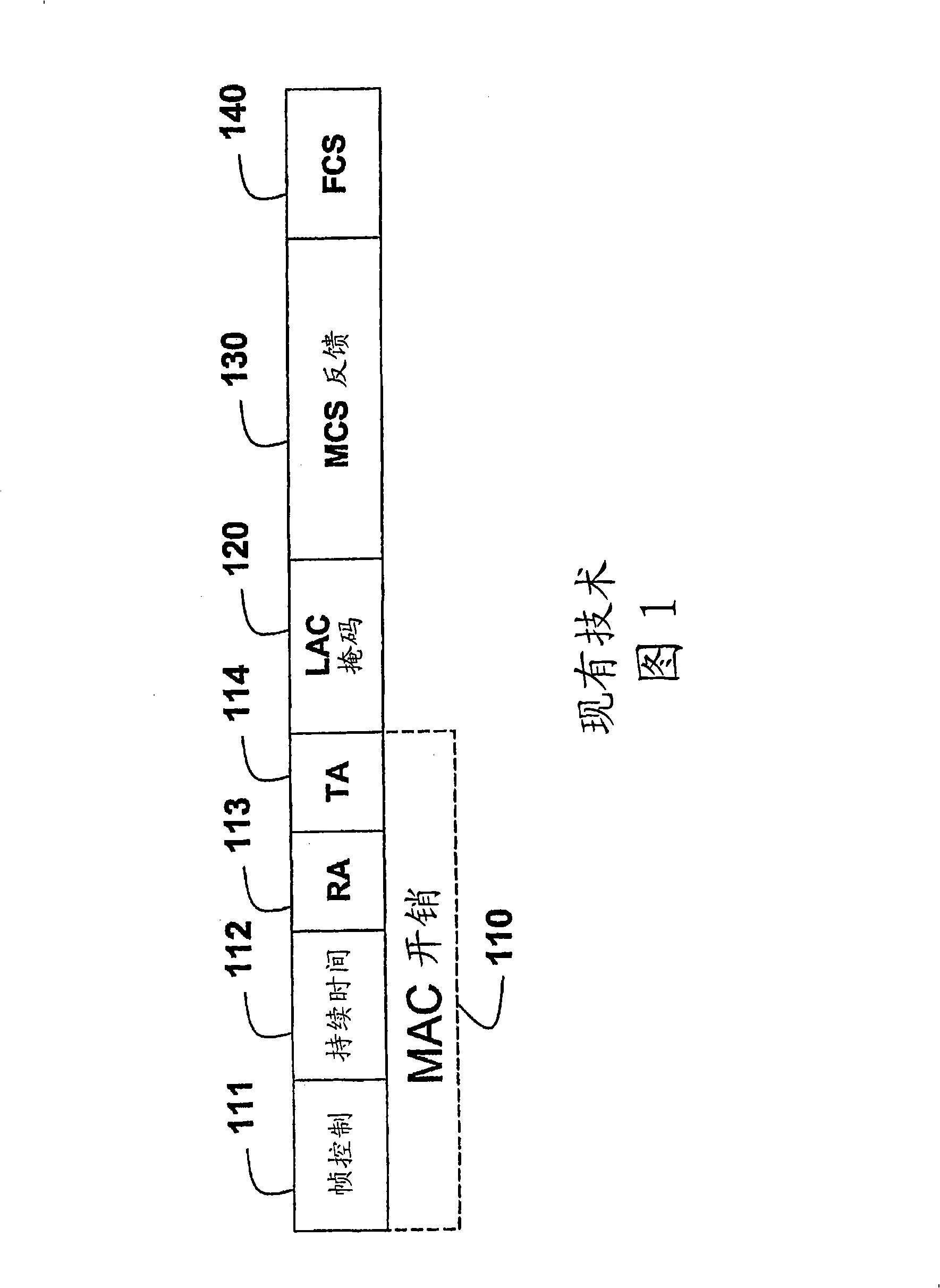
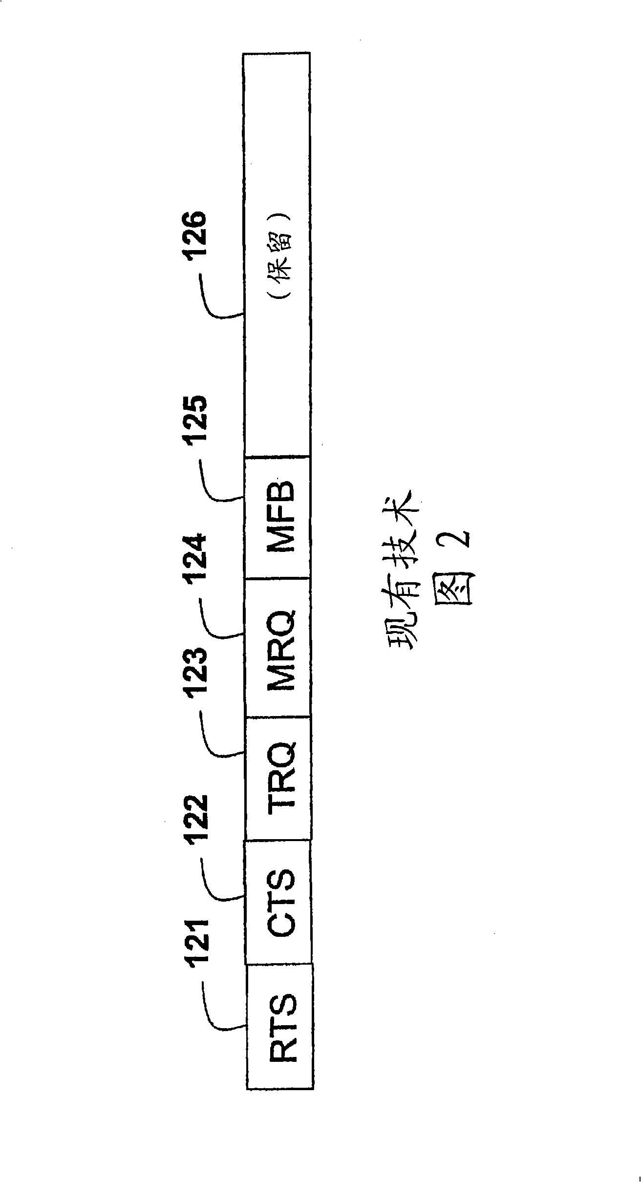
A method selects antennas in a multiple-input, multiple-output (MIMO) wireless local area network (WLAN) that includes a plurality of stations, and each station includes a set of antennas. Plural consecutive packets, received at a station, include plural consecutive sounding packets. Each sounding packet corresponds to a different subset of the set of antennas, and at least one of the plural consecutive packets includes a high throughput (HT) control field including a signal to initiate antenna selection and a number N indicative of a number of sounding packets which follow the at least one packet including the HT control field and which are to be used for antenna selection. A channel matrix is estimated based on a characteristic of the channel as indicated by the received N sounding packets, and a subset of antennas is selected according to the channel matrix.; Station and computer program product embodiments include similar features.

Description

[0001] related application [0002] This application is a partial continuation of PCT application PCT / US2005 / 042358 "Method for Selecting Antennas and Beams in MIMO Wireless LANs" filed by Gu et al. on November 21, 2005, and claims the priority of this PCT application. technical field [0003] The present invention relates generally to multiple-input multiple-output (MIMO) wireless local area networks, and more particularly to selecting antennas and beams in such networks. Background technique [0004] MIMO technology can significantly increase system capacity in the distributed environment of wireless networks. However, using more antennas increases hardware complexity and cost because in a typical system each transmit / receive antenna requires a separate RF chain, including modulator / demodulator, analog-to-digital (AD) / digital-to-analog (DA) converters, up / down converters, and power amplifiers. In addition, as the number of antennas increases, the processing complexity of...

Claims


Application Information

Patent Timeline
Patent Type & Authority Applications(China)
IPC IPC(8): H04B7/00
CPCH04B7/0634H04B7/0691H04B7/0636H04B7/0695H04B7/061H04B7/0874H04B7/088H04W84/12H04B7/0626H04B7/0608
Inventor 顾大庆张鸿远张锦云安德里亚·F·莫利萨奇
Owner MITSUBISHI ELECTRIC RES LAB INC
Learn More