Sludge crushing feeder

A feeder and sludge technology, applied in the field of sludge crushing feeder, can solve the problems of difficult to achieve continuous and uniform feeding, slow conveying speed, difficult recycling of waste materials, etc., to ensure normal production and application, not easy to pollute Mud clumps, good balling effect

Inactive Publication Date: 2010-04-14
唐承祯
View PDF5 Cites 0 Cited by
  • Summary
  • Abstract
  • Description
  • Claims
  • Application Information

AI Technical Summary

Problems solved by technology

[0002] The sludge of converter steelmaking in iron and steel plants contains 30%-50% iron. These sludges can be returned to the furnace for steelmaking to realize the policy of circular economy utilization. At present, the feeding equipment existing in China adopts screw feeding. The viscosity of the mud is high, and it is not easy to break after forming a mass. When the sludge sticks to the feeding device, it hinders the rotation of the feeding screw, and it is difficult to achieve continuous and uniform feeding. The conveying speed is slow and the efficiency is low. It is difficult to realize the recycling of waste materials. Effect

Method used


Image

  • Sludge crushing feeder
  • Sludge crushing feeder
  • Sludge crushing feeder

Examples


Embodiment Construction

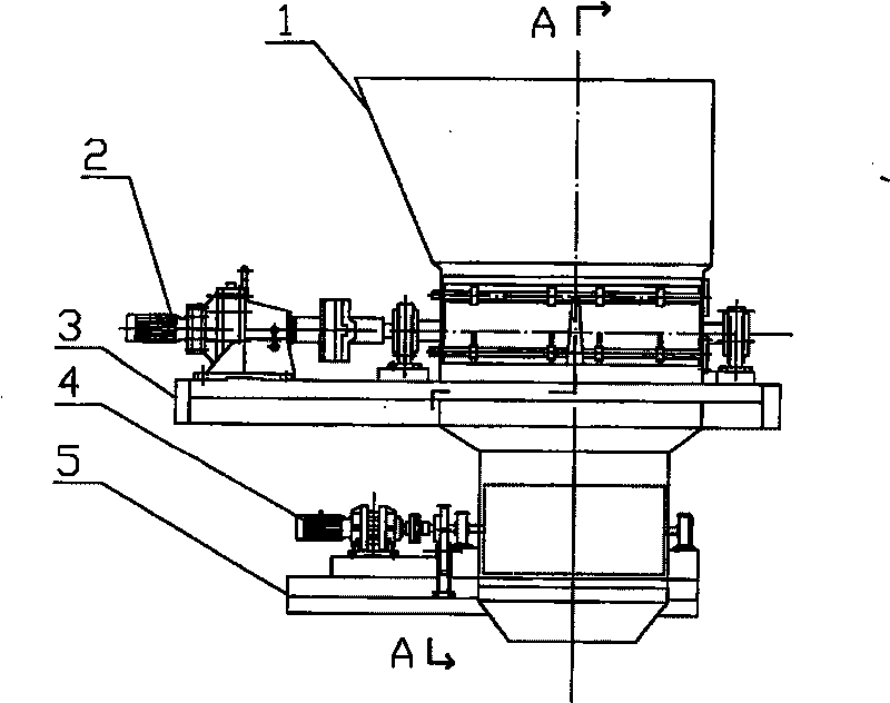
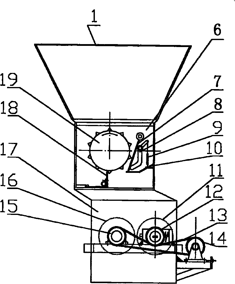
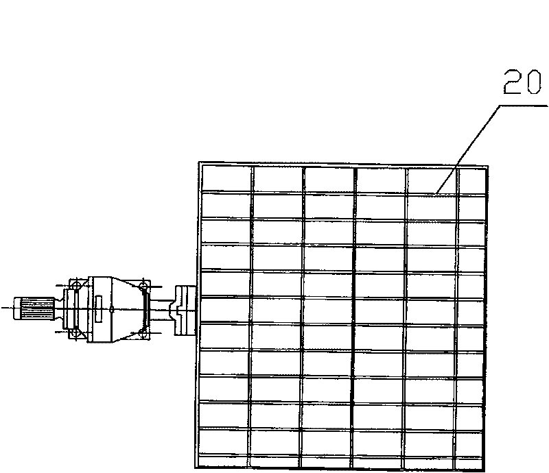
[0013] like figure 1 , figure 2 and image 3 A kind of specific embodiment shown, it comprises hopper 1, motor I 2, feeding part frame 3, motor II 4, breaks part frame 5, feeding box 6, buffer plate 7, crank arm 8, pulls Spring 9, material distribution tooth 10, driven crushing roller 11, driven sprocket 12, chain 13, reversing sprocket 14, driving sprocket 15, active crushing roller 16, crushing material box 17, scraping device 18. Feed roller 19 and grate plate 20.

[0014] Motor I 2, feeding part frame 3, feeding box 6, buffer plate 7, crank arm 8, extension spring 9, material distributing tooth 10, scraping device 18 and feeding roller 19 form feeding part. like figure 2 As shown, the buffer plate 7, the crank arm 8, the extension spring 9, the distributing tooth 10, the scraping device 18 and the feeding roller 19 are arranged in the feeding box 6, and the scraping device 18 is arranged under the feeding roller 19, The scraping device 18 can remove the remaining ma...


PUM


Abstract

The invention discloses a sludge crushing feeder, which comprises a hopper, a feeding part and a crushing part which are arranged from the top down, wherein, the feeding part comprises a feed box, a feeding part stander and a feed roller which is arranged inside the feed box; the crushing part comprises a crushing hopper, a crushing part stander and a crushing roller set which is arranged inside the crushing hopper; and the feed roller and the crushing roller set are respectively connected with a drive unit which respectively drives the feed roller and the crushing roller set to rotate. The sludge crushing feeder changes the prior spiral feeding means and adopts a two-stage drum for feeding, thereby the phenomenon of sludge agglomeration is difficult to generate and sludge can be continuously and uniformly conveyed onto a mixing belt and can be completely uniformly mixed with mineral powder before sintering on the mixing belt. The sludge crushing feeder successfully solves the problemsof spherulization, cementation, equipment blockage and so on which are common during the mixing process of steel-making and iron-making sludge and the mineral powder before sintering.

Description

(1) Technical field [0001] The invention relates to a steelmaking and ironmaking sludge conveying equipment, in particular to a sludge crushing feeder. (2) Background technology [0002] The sludge of converter steelmaking in iron and steel plants contains 30%-50% iron. These sludges can be returned to the furnace for steelmaking to realize the policy of circular economy utilization. At present, the feeding equipment existing in China adopts screw feeding. The viscosity of the mud is high, and it is not easy to break after forming a mass. When the sludge sticks to the feeding device, it hinders the rotation of the feeding screw, and it is difficult to achieve continuous and uniform feeding. The conveying speed is slow and the efficiency is low. It is difficult to realize the recycling of waste materials. Effect. (3) Contents of the invention [0003] The technical problem to be solved by the present invention is to provide a roller-type sludge crushing feeder that can con...

Claims


Application Information

Patent Timeline
Patent Type & Authority Patents(China)
IPC IPC(8): C02F11/00
Inventor 张瑞堂战玉生方贻留李真明唐富国
Owner 唐承祯
Why Eureka
Try Eureka