Camera module group image test system and method

A camera module and testing system technology, applied in the camera body, camera, photography and other directions, can solve the problems of large light box, waste of test man-hours, large space required for testing, etc., to reduce test space and test man-hours. Effect

Inactive Publication Date: 2008-11-19
HONG FU JIN PRECISION IND (SHENZHEN) CO LTD +1
View PDF0 Cites 5 Cited by
  • Summary
  • Abstract
  • Description
  • Claims
  • Application Information

AI Technical Summary

Problems solved by technology

[0006] Each test item needs to be tested separately, which seriously wastes testing man-hours;
[0007] When the test chart is large, the required light box is also relatively large, and in order to fully image the test chart, the test fixture needs to be far away from the test chart, resulting in a large space for testing

Method used


Image

  • Camera module group image test system and method
  • Camera module group image test system and method
  • Camera module group image test system and method

Examples


Embodiment Construction

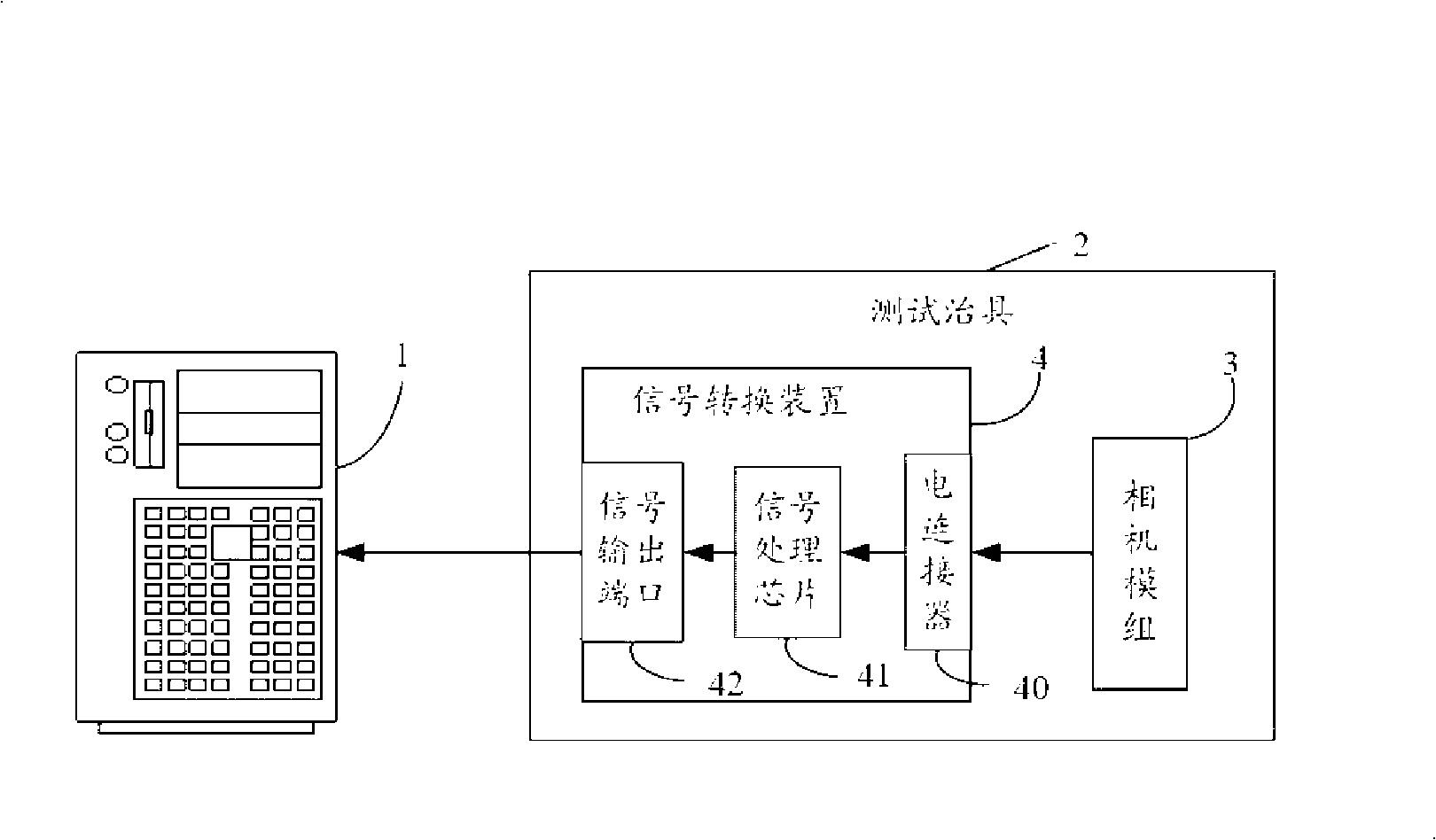
[0023] refer to figure 1 Shown is a system architecture diagram of a preferred embodiment of the image testing system for the camera module of the present invention. The video test system mainly includes a computer 1 and a test fixture 2 . The test fixture 2 is used to install the camera module 3 to be tested, and is provided with a mounting hole for the camera module 3 to be installed and a fastener (not shown) on the edge of the mounting hole. The measured camera module 3 is stably fixed on the mounting hole. A signal conversion device 4 is installed on the test fixture 2 for converting the image signal output by the camera module 3 to be tested into an image signal format that can be recognized by the computer 1 . The signal conversion device 4 includes an electrical connector 40 for connecting the camera module 3 to be tested, at least one signal processing chip 41 for signal conversion and a signal output port 42 for connecting to the computer 1 . The electrical connec...


PUM


Abstract

The invention provides an image test system for a camera module group, which comprises a computer and a test fixture; the computer is connected with the test fixture. A camera module group and a signal conversion device are arranged on the test fixture. The computer comprises an area segmentation module which is used to segment the image into a plurality of test areas, an image test module which tests the test items of each test area segmented by the area segmentation module, and an operation and judgment module which is used to judge whether the test value of each test item in each test area exceeds the corresponding preset normative value. The invention also provides an image test method for the camera module group. The invention uses an integrated test chart to make integrated test to black corners, colors, gray scales, analysis and other test items, so as to effectively reduce the working hours and further reduce the test space through a vertical test method.

Description

technical field [0001] The invention relates to a testing technology of a camera module, in particular to an image testing system and method of a camera module. Background technique [0002] The image test of the camera module includes test items such as shading, color, gray scale and resolution. Normally, each test item is tested in its corresponding test station. The test station includes: a computer, a test fixture, a light box, and the like. Wherein, the light box includes a light source and a test chart. The camera module to be tested is installed on the test fixture, the focal length of the camera module is adjusted by moving the test fixture, the test chart is imaged, and the test item is tested by the corresponding test program in the computer. [0003] According to the traditional image test method, when testing the test items such as vignetting, color, gray scale and resolution of the camera module, each test item needs a corresponding test station, each test st...

Claims


Application Information

Patent Timeline
Patent Type & Authority Applications(China)
IPC IPC(8): G03B43/00
CPCG03B17/00H04N17/002
Inventor 吴炯升郑百祥陈永州
Owner HONG FU JIN PRECISION IND (SHENZHEN) CO LTD
Why Eureka
Try Eureka