Valve gear

A technology of valve device and valve body, which is applied in the direction of valve device, valve operation/release device, valve details, etc., can solve the problems such as difficulty in increasing the pressurization pressure, insufficient switching of the open state, etc., and achieve reliable and smooth cut-off state and The switching of the open state and the effect of miniaturization

Inactive Publication Date: 2008-11-26
ALPS ALPINE CO LTD
View PDF1 Cites 34 Cited by
  • Summary
  • Abstract
  • Description
  • Claims
  • Application Information

AI Technical Summary

Problems solved by technology

[0008] However, in the description of Patent Document 1, the center bottom of the valve body is formed with a flat surface, and the pressure from the fluid acts in the same direction as the center bottom, so it is difficult to increase the pressurizing force.
In addition, when the valve is switched from the shut-off state to the open state by pressurizing with a larger than necessary pressure, the center bottom of the valve body side sticks to the valve seat, so that the switching to the open state becomes insufficient. question
In addition, since an actuator that generates a larger pressurization force is required, there is also a problem that the size of the valve device tends to increase.

Method used


Image

  • Valve gear
  • Valve gear
  • Valve gear

Examples


Embodiment Construction

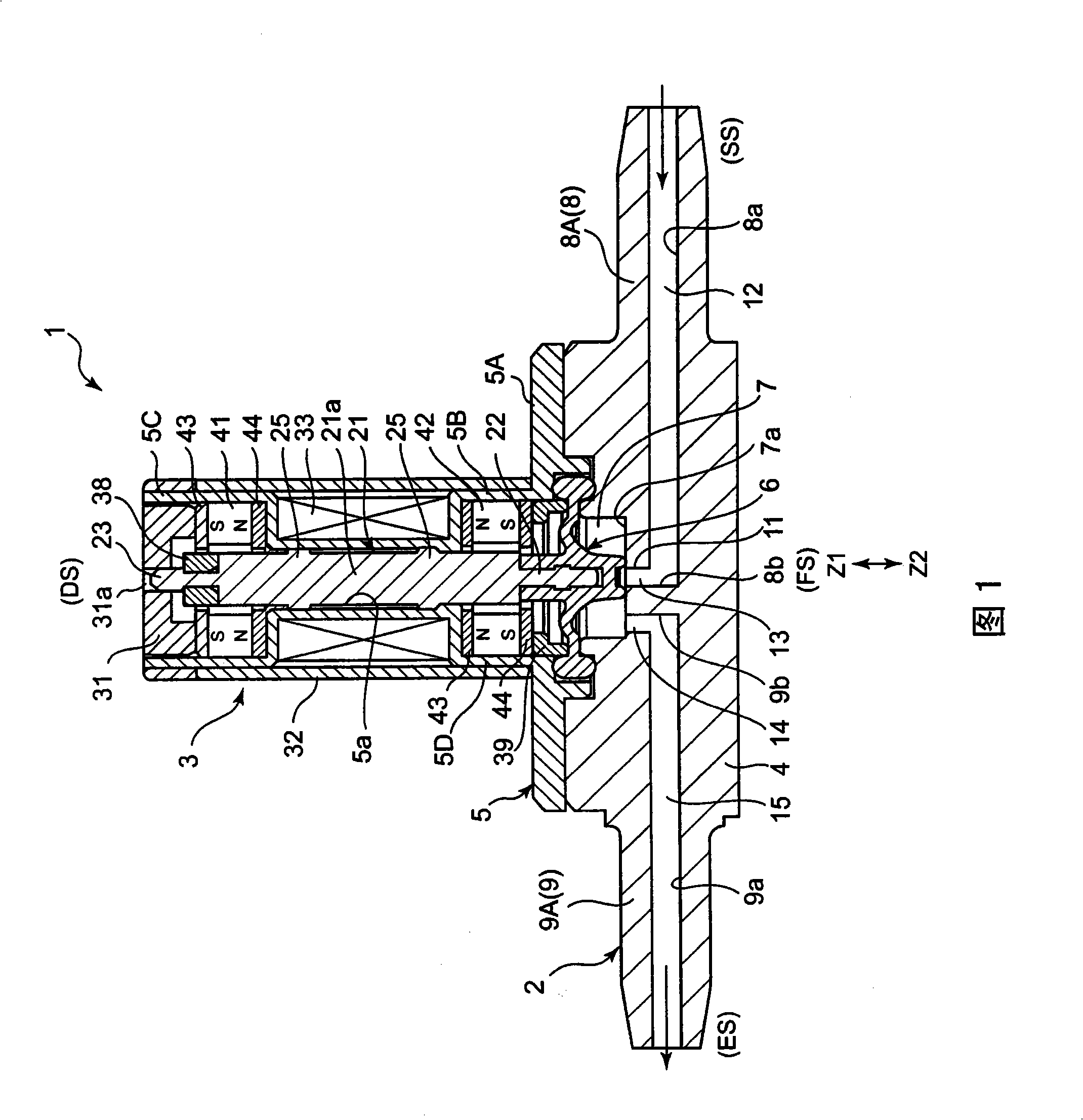
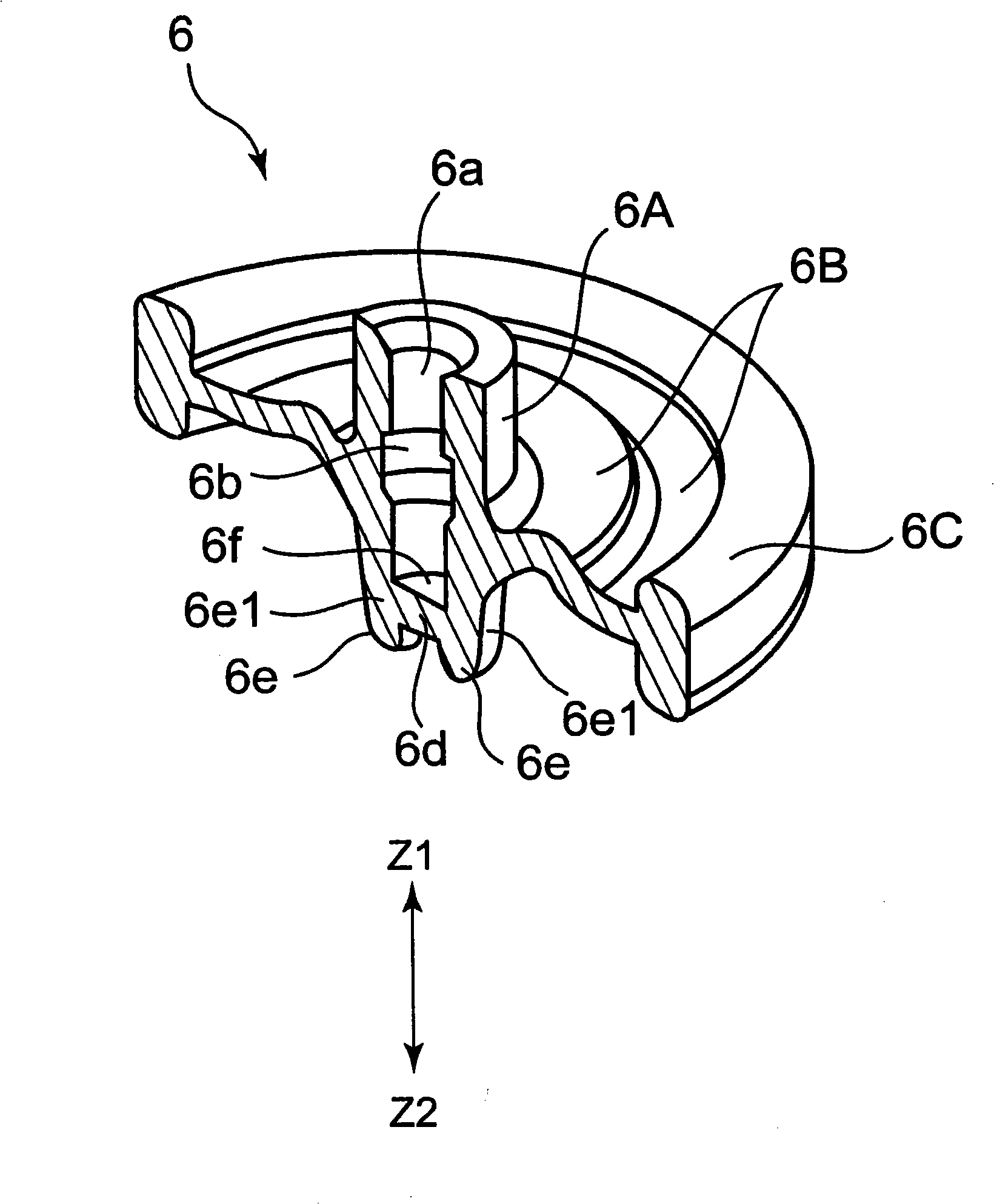
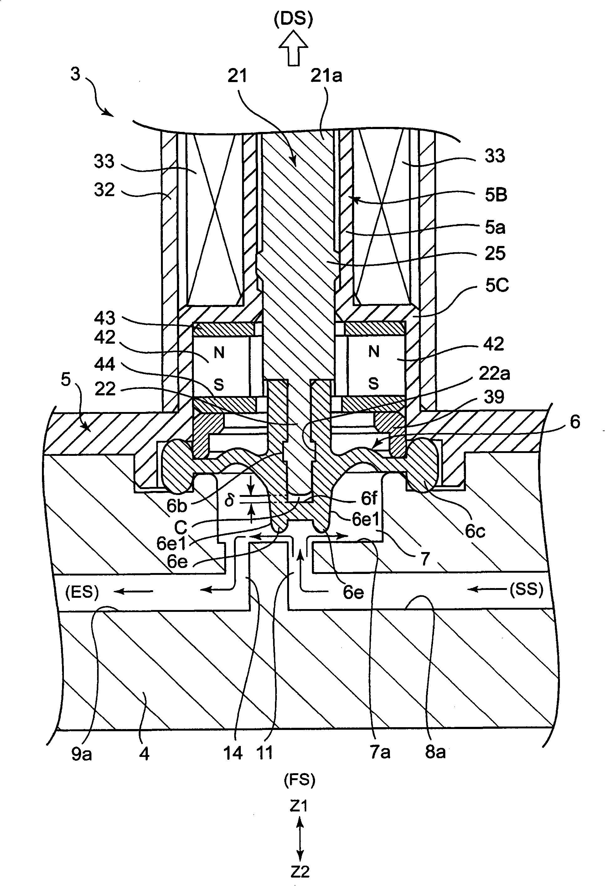
[0030] 1 is a cross-sectional view showing a valve device according to an embodiment of the present invention, figure 2 is a perspective sectional view showing a valve body of a valve device, image 3 and Figure 4 Indicates the operating state of the valve device, image 3 is an enlarged sectional view showing an open state, Figure 4 It is an enlarged sectional view showing a cut state.

[0031] As shown in FIG. 1 , a valve device 1 shown in this embodiment includes a valve main body 2 and an electromagnetic actuator (drive mechanism) 3 . The upper side of the valve device 1 in the figure is the drive side DS where the electromagnetic actuator (drive mechanism) 3 is arranged, and the lower side is the fluid side FS of the supply flow path. In addition, the left side of the valve main body 2 in the figure is the supply side SS of the fluid, and the right side is the discharge side ES of the fluid. Therefore, in this embodiment, the fluid flows from the supply side SS on ...


PUM


Abstract

The invention provides a valve device, wherein a valve is reliably sealed even if by small force with little leakage. Under the cutting state of a movable axis (21) moving downwards, a ring rib (6e) bunts against an open end of a first perforation hole (11) which forms an inflow path (12) around thereby jamming the path. A cavity part (C) is formed between an inner bottom (6f) inside an insertion part (6a) of a valve (6) at the front of the movable axis (21), therefore, the ring rib (6e) can fully performs elastic deformation, to reliably seal the open end of the first perforation hole (11), and obtain a valve device with little leakage.

Description

technical field [0001] The present invention relates to a valve device related to a valve device for opening and closing a flow path, so that the valve can be reliably shut off even by a particularly small pressurizing force. Background technique [0002] In a conventional valve device, an actuator for displacing the movable shaft in the axial direction is provided, and a valve body made of silicone rubber or the like having excellent flexibility is attached to the tip of the movable shaft. [0003] In this valve device, when the actuator is driven to displace the movable shaft in the axial direction, the valve body provided at the front end comes into contact with the valve seat. At this time, since the valve body blocks the outflow path provided on the valve seat, the inflow path and the outflow path can be blocked. [0004] Patent Document 1: Japanese Patent Application Laid-Open No. 2007-16935 (page 11, FIGS. 7 to 9 ) [0005] In the valve device described in the afore...

Claims


Application Information

Patent Timeline
Patent Type & Authority Applications(China)
IPC IPC(8): F16K7/14F16K31/08F16K31/02F16K27/00
Inventor 加藤拓也佐藤秀昭
Owner ALPS ALPINE CO LTD
Why Eureka
Try Eureka