

Foamed resin molding machine and method of operating the same
A technology of foamed resin and operation method, which is applied in the field of foamed resin molding machines, and can solve problems such as damage, failure to take out molded products smoothly, and puncture of ejector pins, etc.
- Summary
- Abstract
- Description
- Claims
- Application Information
AI Technical Summary
Problems solved by technology
Method used
Image

Examples
no. 1 example
[0061]
A first embodiment of the present invention is described below.
[0062]
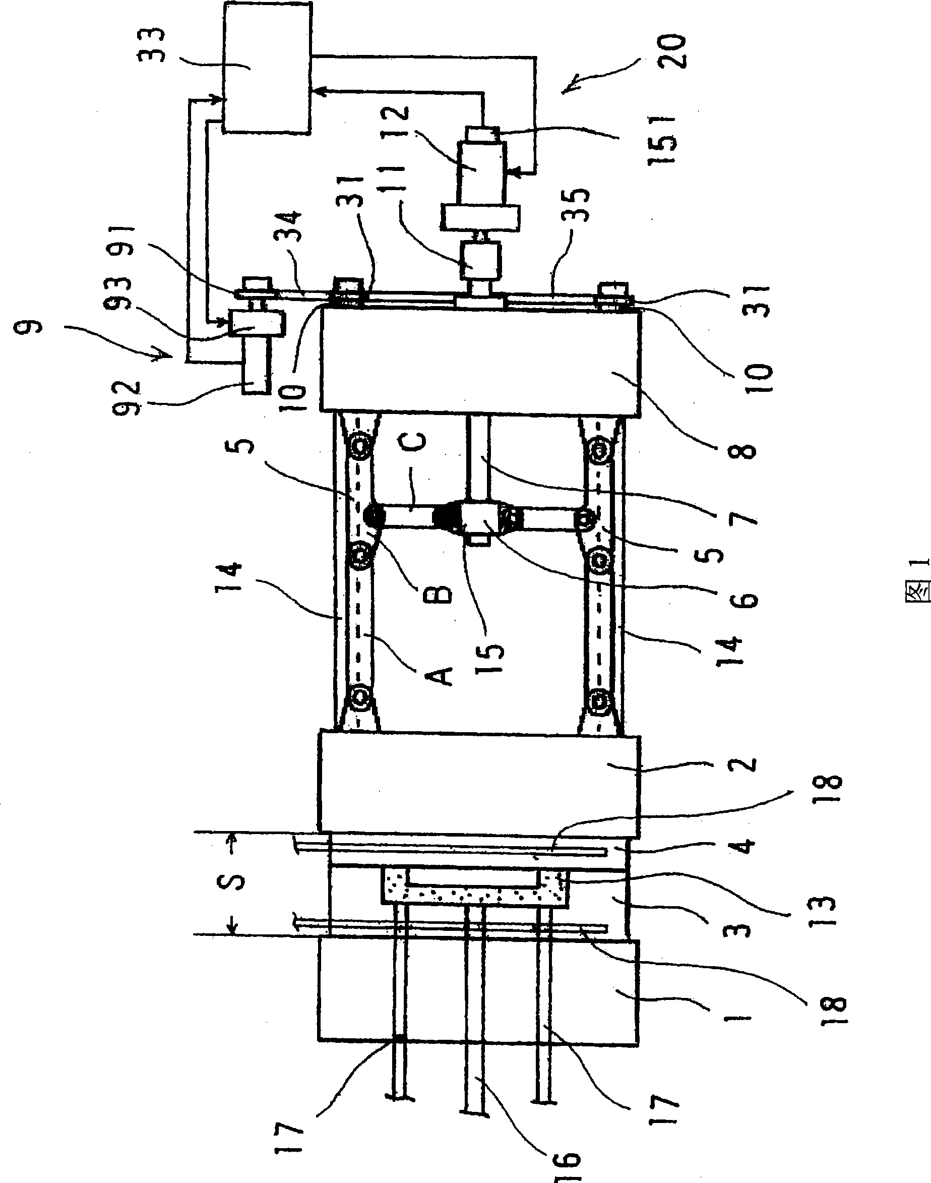
Fig. 1 is a schematic outline view of a foamed resin molding machine of the present invention having a mold opening and closing device. In FIG. 1 , the movable template 2 is reversed relative to the fixed template 1 , and the mold tightening shell 8 is arranged on the right side of the movable template 2 in the figure.
[0063]
The fixed template 1 is equipped with a fixed mold 3, and the movable template 2 is equipped with a movable mold 4. The cavity 13 is formed in a mold composed of the fixed mold 3 and the movable mold 4 . The fixed die 3 is equipped with a material feeder 16, and ejector pins 17 passing through the fixed die 1 for extruding the molded product. The fixed mold 3 and the movable mold 4 are each equipped with pipes 18 for supplying water, steam and air inside.
[0064]
Four tie rods 14 are provided to pass through the movable platen 2 and the mold tightening case 8 , a...
no. 2 example
[0084]
A second embodiment of the present invention is described below.
[0085]
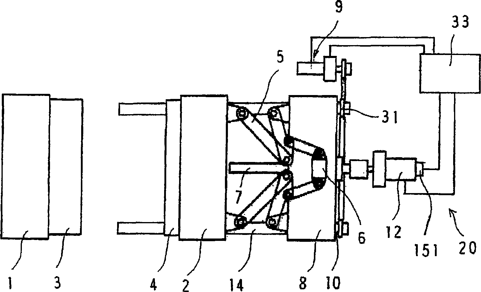
Fig. 6 is a schematic outline view of a foamed resin molding machine having a mold tightening force adjusting mechanism. In FIG. 6 , the movable template 2 is reversed relative to the fixed template 1 , and the mold clamping shell 8 is arranged on the right side of the movable template 2 in the figure.
[0086]
The fixed template 1 is equipped with a fixed mold 3, and the movable template 2 is equipped with a movable mold 4. The mold cavity 13 is formed in a mold composed of the fixed mold 3 and the movable mold 4 . The fixed die 3 is equipped with material feeders, and ejector pins (not shown) for extruding the molded product through the fixed die. The fixed mold 3 and the movable mold 4 are each equipped with pipes (not shown) for supplying water, steam and air inside.
[0087]
Four tie rods 14 are arranged to pass through the movable template 2 and the mold tightening shell 8, and th...
no. 3 example
[0103]
A third embodiment of the present invention is described below.
[0104]
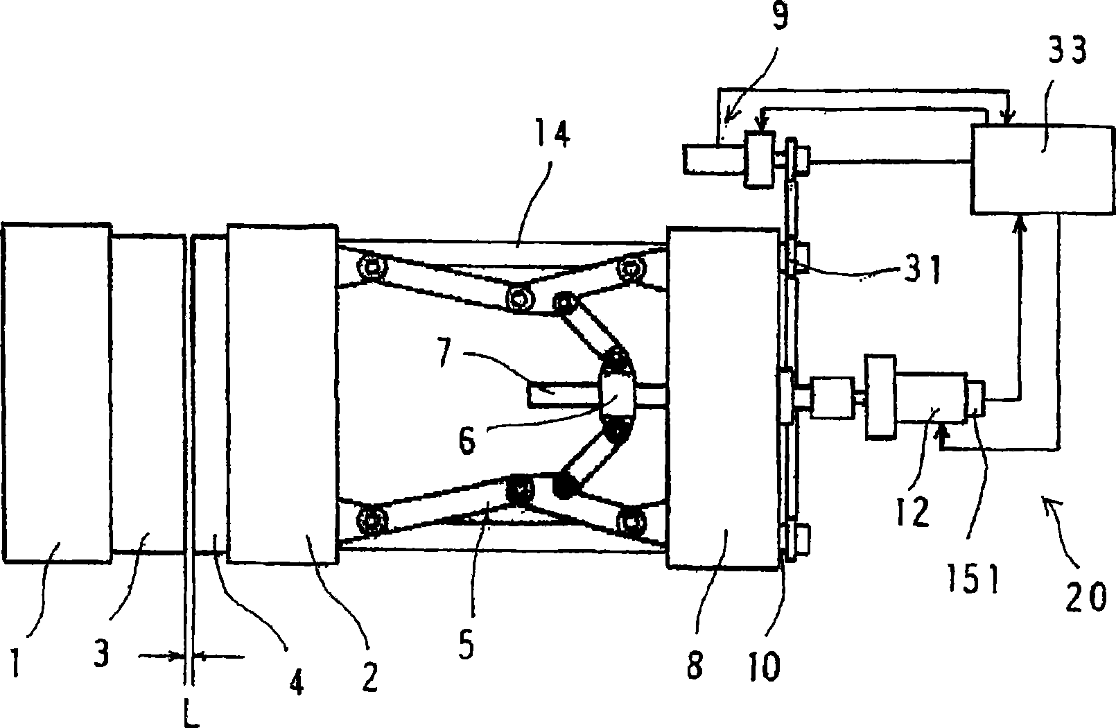
9 and 10 show a foamed resin molding machine for realizing the ball screw system of the present invention. In the figure, the movable template 2 is reversed relative to the fixed template 1 . These templates 1, 2 are equipped with a fixed mold 3 and a movable mold 4 respectively. The center of the fixed mold 3 is equipped with a material feeding device 16 for emitting material particles by injecting air. Two ball screws 105 , 106 are provided through nut portions 107 at opposite positions across the movable die 4 .
[0105]
A high-speed moving mechanism 108 for the movable template 2 is provided at one end of one ball screw 105 , and a low-speed moving mechanism 109 for the movable template 2 is provided at one end of the other spherical screw 106 . A power transmission member for transmitting rotation of one ball screw 105 or 106 to the other ball screw is provided between these ball scre...
PUM
| Property | Measurement | Unit |
|---|---|---|
| width | aaaaa | aaaaa |
Abstract
Description
Claims
Application Information