Quick closing mechanism of isolating switch and isolating switch

A kind of isolation switch, fast technology, applied in electrical switches, air switch parts, high-voltage air circuit breakers and other directions, can solve the problems of poor contact stability, slow closing instantaneous speed, etc., to achieve stable contact, strong closing force, fast The effect of closing

Pending Publication Date: 2021-01-29
XIAMEN HONGFA ELECTRICAL SAFETY & CONTROLS CO LTD
View PDF1 Cites 0 Cited by
  • Summary
  • Abstract
  • Description
  • Claims
  • Application Information

AI Technical Summary

Problems solved by technology

[0003] Application No. 201110274291.X, titled a closing mechanism of a disconnector and a Chinese invention application for a disconnector including the closing mechanism, discloses that a connecting rod arranged in a chute is controlled by an operating handle to realize closing. structure, the scheme is completely converted into the closing stroke through the formation of the operating handle, the closing speed is slow at the moment of closing, and the contact stability is poor

Method used


Image

  • Quick closing mechanism of isolating switch and isolating switch
  • Quick closing mechanism of isolating switch and isolating switch
  • Quick closing mechanism of isolating switch and isolating switch

Examples


Embodiment 1

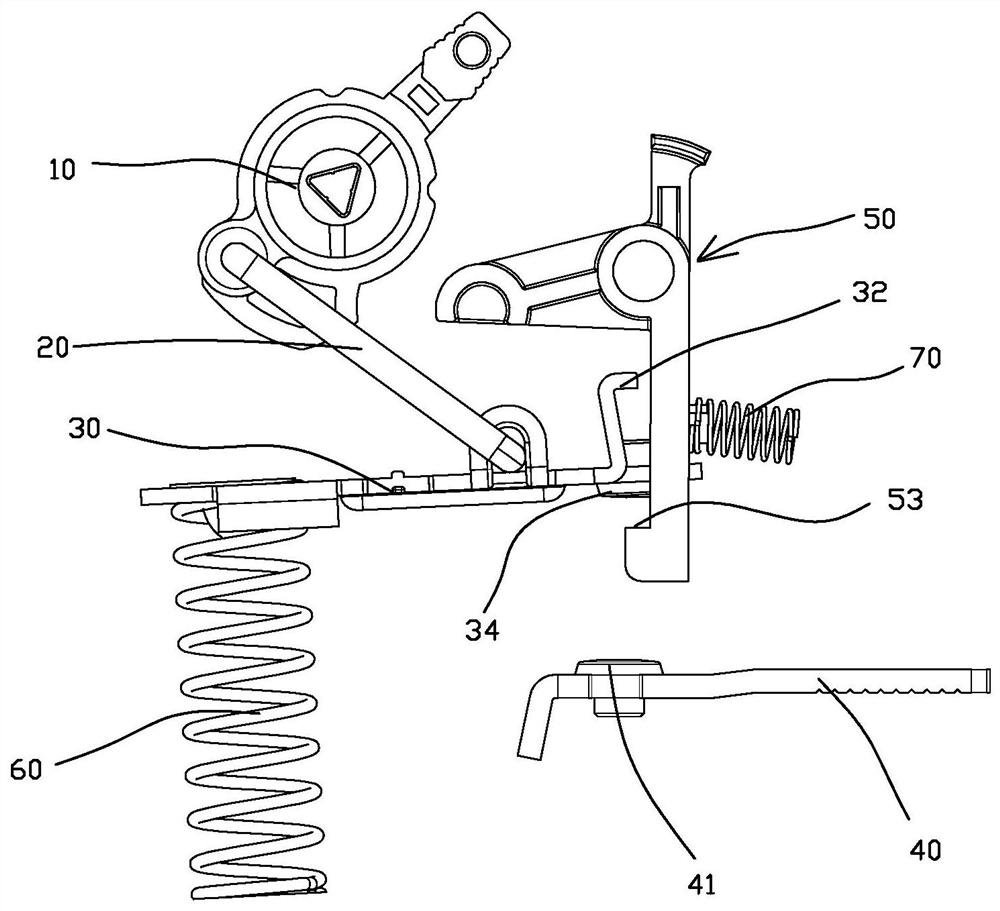
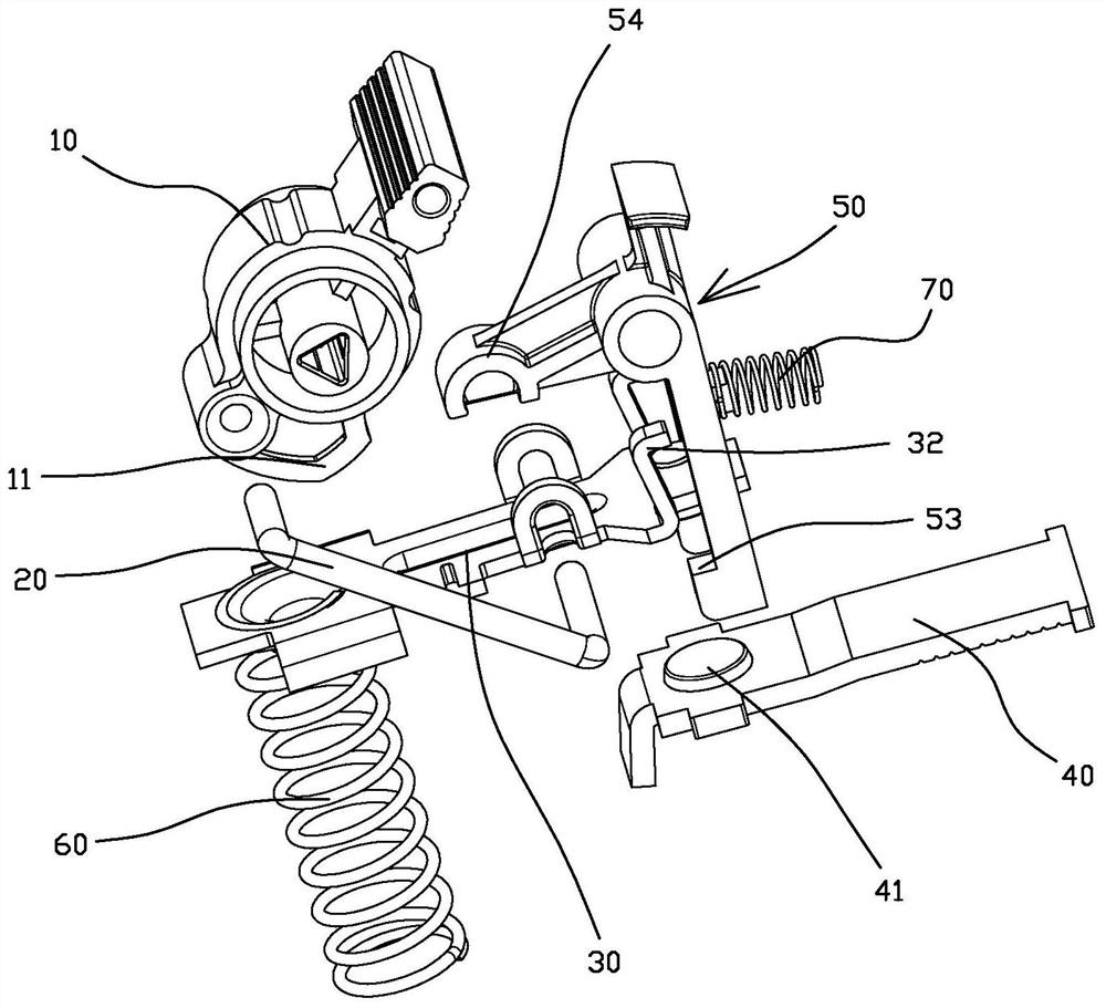
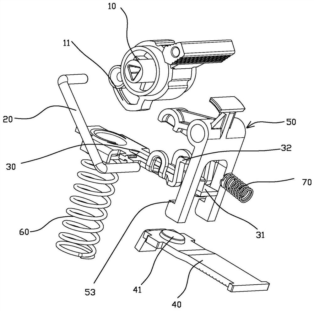
[0043] refer to Figure 1 to Figure 9 As shown, a quick closing mechanism of a disconnector provided in this embodiment includes a moving contact bracket 30 with a moving contact 34, a static contact bracket 40 with a static contact 41, an operating handle 10, a connecting Rod 20, chute, elastic driving member 60 and quick-fitting member 50; specifically, the chute is directly formed in the housing of the isolating switch. Figure 1 to Figure 9 not shown, please refer to the attached Figure 10 The chute 80 formed in the first housing 1001.

[0044]The fast closure 50 is hingedly arranged and extends to form a limited step 53. The movable contact 34 is arranged on the first end 301 of the movable contact bracket 30, and the first end 301 of the movable contact bracket 30 is further extended by Corresponding to the hook portion 32 of the limit step 53, the elastic driving member 60 acts on the second end 302 of the moving contact bracket 30, one end of the connecting rod 20 i...

Embodiment 2

[0064] The quick closing mechanism of the isolating switch provided in this embodiment is roughly the same as the quick closing mechanism of the isolating switch provided in the first embodiment, the difference lies in the orientation and implementation of the cooperation between the limit step 53 and the hook part 32 Example 1 is opposite, and the driving limit step 53 is opposite to the swinging direction of the hook portion 32 . Specifically referring to the accompanying drawings, in this embodiment, specifically, as Figure 17 As shown, the hook portion 32 is toward the second end 302 of the moving contact bracket 30, that is, as Figure 18 As shown, when assembled on the isolating switch, the hook portion 32 is set towards the left, while the limit step 53 of the quick closure 50 is set towards the right to match the hook portion 32, when the second stage is switched to the third stage ,Such as Figure 18 , 19 As shown, the driving convex part 11 of the operating handl...

Embodiment 3

[0067] The quick closing mechanism of the isolating switch provided in this embodiment is roughly the same as the quick closing mechanism of the isolating switch provided in the first embodiment, except that in the third stage, the limit step of the quick closing member 50 53 swings away from the moving contact bracket 30 to get away from the hook part 32 in different ways, refer to Figure 20 , 21 As shown, in this specific embodiment, the limit step 53 is inclined at the first stage, and when the second stage is switched to the third stage, the hook portion 32 is under the transmission pressure of the connecting rod 20 (ie, the operation The pull of the handle 10 forms a relative slide with the limit step 53 under the action of the transmission pressure applied by the connecting rod 20 , and then drives the limit step 53 of the quick closure 50 to swing away from the contact bracket 30 to give way. In this way, by realizing automatic detachment after reaching a certain pres...


PUM


Abstract

The invention provides a quick closing mechanism of an isolating switch and the isolating switch with the quick closing mechanism. The quick closing mechanism of the isolating switch comprises a moving contact support with a moving contact, a static contact support with a static contact, an operating handle, a connecting rod, a sliding groove, an elastic driving piece and a quick closing piece. The quick closing piece is hinged and extends to form a limiting step, the moving contact is arranged at a first end of the moving contact support, a first end of the moving contact support further extends to form a hook portion corresponding to the limiting step, the elastic driving piece acts on a second end of the moving contact support, one end of the connecting rod is connected with the operating handle, and the other end of the connecting rod is connected with the middle position of the moving contact support and is in sliding fit in the sliding groove. And a blocking and limiting structure of the quick closing piece is arranged, so that the closing action of the moving contact support can store energy at first and then release energy to realize quick closing, the closing force is large, the speed is high, and the contact is stable.

Description

technical field [0001] The invention relates to the field of electrical switches, in particular to a quick closing mechanism of an isolating switch and an isolating switch with the quick closing mechanism. Background technique [0002] Isolating switch is a kind of electrical appliance widely used in switching electrical appliances, which plays an isolation role in the circuit. The main feature of the knife switch is that it has no arc extinguishing ability, and can open and close the circuit under normal load current. The isolating switch is mainly composed of insulating part, conductive part, supporting base or frame, closing mechanism and operating mechanism (drive module). Among them, the operating mechanism is used to control the closing, opening and testing status of the isolating switch. The closing mechanism receives the torque of the operating mechanism and transmits the movement to the moving contact to complete the opening and closing actions of the disconnector...

Claims


Application Information

Patent Timeline
Patent Type & Authority Applications(China)
IPC IPC(8): H01H31/02
CPCH01H31/026
Inventor 龚旺辛克均林桌勇周燕海
Owner XIAMEN HONGFA ELECTRICAL SAFETY & CONTROLS CO LTD
Why Eureka
Try Eureka