Circuit breaker spring operating mechanism

An operating mechanism, circuit breaker technology, applied in high-voltage air circuit breakers, circuits, contact vibration/shock damping, etc., can solve the problems of low stability and reliability, low positioning accuracy, low service life, etc. Good consistency, high positioning accuracy, reducing the effect of welding parts

Active Publication Date: 2020-09-18
NANJING NARI GROUP CORP +1
View PDF12 Cites 3 Cited by
  • Summary
  • Abstract
  • Description
  • Claims
  • Application Information

AI Technical Summary

Problems solved by technology

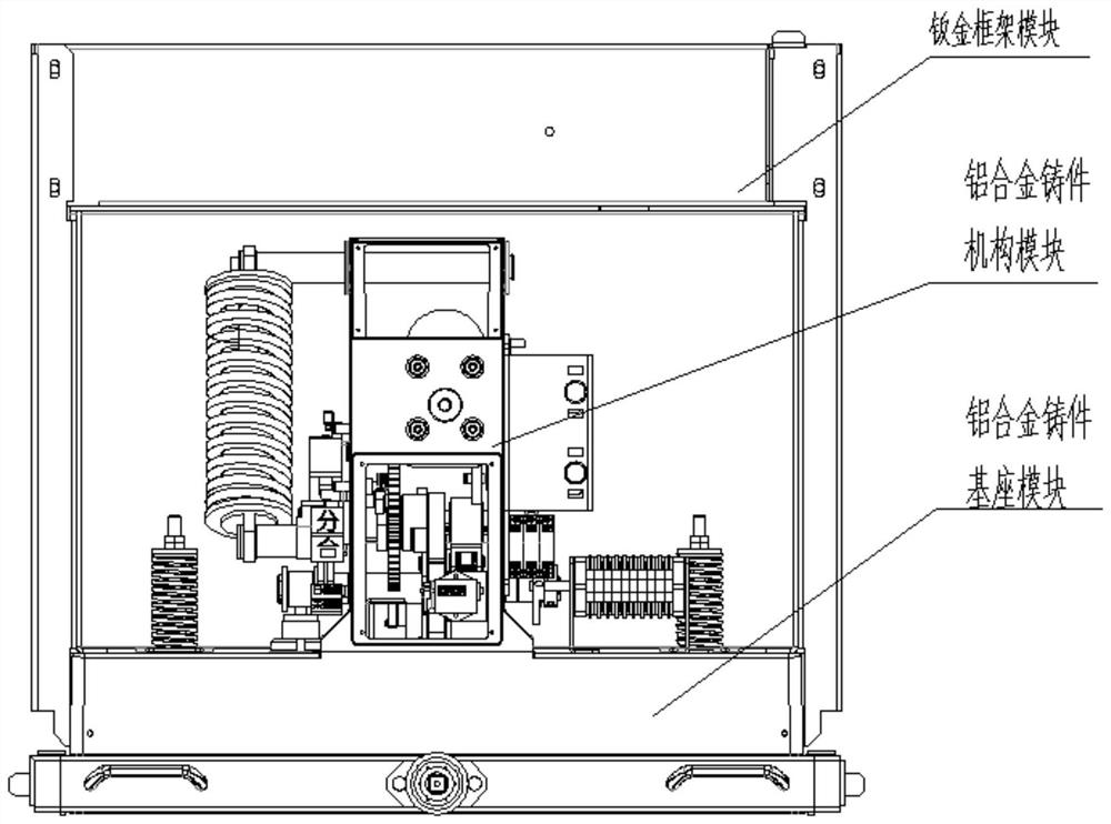
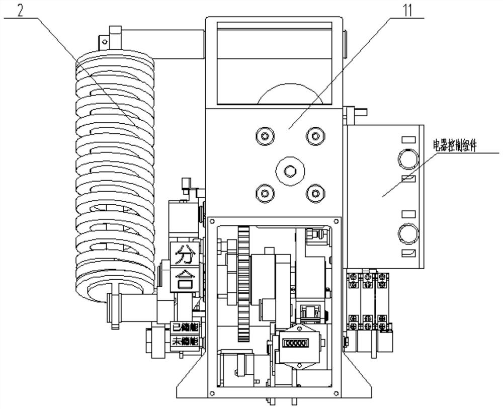
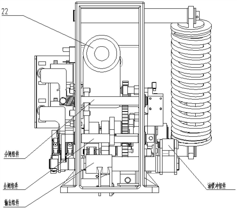
The existing vacuum circuit breaker spring operating mechanism has problems such as complex structure, large volume, low stability, and difficult maintenance in the later stage
At present, the integrated spring operating mechanism and single-component spring operating mechanism widely used in China mostly adopt welded frame structure, which is prone to welding deformation and low positioning accuracy; the existing circuit breaker operating mechanism has a large number of components and product stability. and low reliability; the existing circuit breaker operating mechanism also has the disadvantages of large impact force and low service life when closing and opening

Method used


Image

  • Circuit breaker spring operating mechanism
  • Circuit breaker spring operating mechanism
  • Circuit breaker spring operating mechanism

Examples


Embodiment Construction

[0039] In order to make the technical means, creative features, goals and effects achieved by the present invention easy to understand, the present invention will be further described below in conjunction with specific embodiments.

[0040] It should be noted that, in the description of the present invention, the terms "front", "rear", "left", "right", "upper", "lower", "inner", "outer" and the like indicate orientations or positions The relationship is based on the orientation or positional relationship shown in the drawings, and is only for the convenience of describing the present invention and does not require that the present invention must be constructed and operated in a specific orientation, and thus should not be construed as a limitation of the present invention. The terms "front", "rear", "left", "right", "upper" and "lower" used in the description of the present invention refer to the directions in the drawings, and the terms "inner" and "outer" refer to is the dir...


PUM


Abstract

The invention discloses a spring operating mechanism of a circuit breaker. The mechanism comprises a switching-on assembly, an switching-off assembly, a transmission assembly and an output assembly which are connected in a shell frame; the output assembly comprises an output shaft and an output crank arm connected to the output shaft. The switching-on assembly comprises a switching-on half shaft and an energy storage maintaining latch connected to the switching-on half shaft. The transmission assembly comprises an energy storage shaft, the energy storage shaft is connected with a closing spring, and the energy storage shaft rotates to compress the closing spring to realize energy storage; the energy storage shaft rotates to drive a first roller on a cam on the energy storage shaft to be incontact connection with the energy storage maintaining latch to achieve energy storage maintaining; the switching-on spring is reset to realize switching-on; the switching-on spring resets to drive aswitching-on keeping latch on the energy storage shaft to rotate, and the switching-on keeping latch is in contact connection with a third roller on the output crank arm to realize switching-on keeping; the switching-off assembly is used for switching-on. According to the invention, part reuse is achieved, the total number of parts is greatly reduced, and the beneficial effects of being simple instructure and high in reliability are achieved.

Description

technical field [0001] The invention relates to the technical field of switchgear control, in particular to a circuit breaker spring operating mechanism. Background technique [0002] As an important switching element in the power system, the circuit breaker plays a role in control and protection. The reliability and intelligence level of its action directly determine the reliability and automation level of power supply and distribution in the power system. The existing vacuum circuit breaker spring operating mechanism has problems such as complex structure, large volume, low stability, and difficult maintenance in the later stage. At present, the integrated spring operating mechanism and single-component spring operating mechanism widely used in China mostly adopt welded frame structure, which is prone to welding deformation and low positioning accuracy; the existing circuit breaker operating mechanism has a large number of components and product stability. And the reliabi...

Claims


Application Information

Patent Timeline
Patent Type & Authority Applications(China)
IPC IPC(8): H01H33/666H01H3/60H01H33/662H01H33/66H01H33/36H01H9/02
CPCH01H33/666H01H3/60H01H33/66207H01H33/66H01H33/6661H01H33/36H01H9/02
Inventor 吴夕科韩冬李传强黄志方黄岷江戴永正谢俊清宗清森王鹏顾宇锋李巍苏和许俊杰
Owner NANJING NARI GROUP CORP
Why Eureka
Try Eureka