Combined type offshore wind power energy storage manner utilizing buoyancy and gravity

A generator and fan technology, applied in the field of combined offshore wind power generation energy storage using buoyancy and gravity, can solve the problems of offshore wind power generation energy storage difficulties and achieve high efficiency

Inactive Publication Date: 2018-08-21
张占海
View PDF0 Cites 2 Cited by
  • Summary
  • Abstract
  • Description
  • Claims
  • Application Information

AI Technical Summary

Problems solved by technology

[0003] In order to solve the problem of difficult energy storage for offshore wind power generation, this method adopts two ways of energy storage: buoyancy and gravity

Method used


Image

  • Combined type offshore wind power energy storage manner utilizing buoyancy and gravity
  • Combined type offshore wind power energy storage manner utilizing buoyancy and gravity

Examples


Embodiment Construction

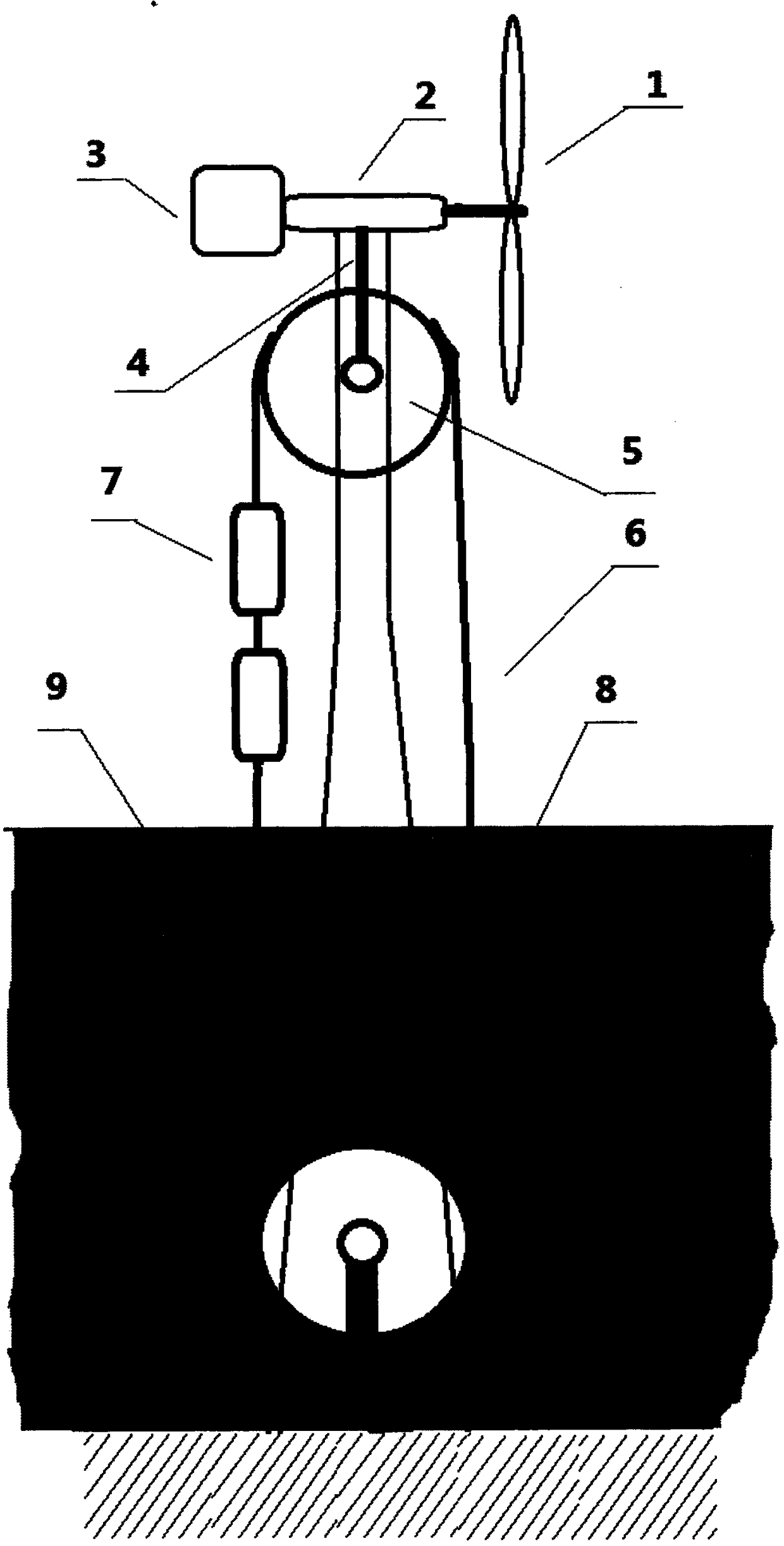
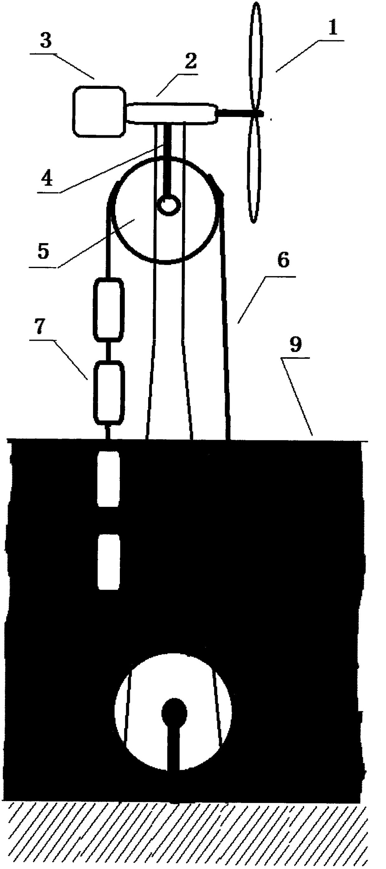
[0009] as attached figure 1 Shown: When the power grid is at the peak of power consumption, the sea breeze blows the fan 1 to rotate to generate power, and the power drives the generator 3 to generate electricity through the transmission 2, and the electric energy is output; when there is wind on the sea and the power grid is at the low peak of power consumption, the sea breeze blows The fan 1 rotates to generate power, the power drives the transmission shaft 4 and the transmission wheel 5 to rotate through the transmission 2, the transmission wheel 5 drives the transmission chain 6 to rotate, the transmission chain 6 drives the buoy 7 downward, and enters the seawater 9, and the bucket 8 is filled with seawater at the same time 9 floats up to the surface of the sea; when there is no wind on the sea and the power grid is at the peak of power consumption, the buoy 7 releases energy upward due to the buoyancy of seawater, and the bucket 8 releases energy downward due to the gravi...


PUM


Abstract

The invention discloses an energy storage manner. According to the energy storage manner, the buoyancy action and the gravity action of seawater are utilized, the energy generated by wind power is stored when offshore wind power is in low-peak demand for electricity, and the energy is released when no wind exists at sea, and a power grid is in the peak demand for electricity.

Description

Technical field: [0001] The field of new energy storage. Background technique: [0002] Offshore wind power resources are very abundant. Due to the intermittent nature of wind power generation, energy storage is more important. The existing offshore wind power generation energy storage generally adopts chemical energy storage, that is, battery energy storage. Chemical energy storage has small capacity, high price and low usage The service life is short, and the post-treatment pollutes the environment. At present, the more advanced one is the offshore wind power pumped storage system developed by the Fraunhofer Institute in Germany. This system uses the pumped storage power station located on the seabed to store energy. When entering deep water, with the help of hollow balls, the pressure of seawater in deep water is used to store energy. When energy storage is required, water is pumped from the sphere with electricity. When energy needs to be released, the water flows throug...

Claims


Application Information

Patent Timeline
Patent Type & Authority Applications(China)
IPC IPC(8): F03D9/25F03D9/14F03B17/02F03G3/00
CPCF03B17/025F03D9/008F03G3/00Y02E10/20Y02E10/72Y02E70/30
Inventor 张占海张红徐兆翮
Owner 张占海
Why Eureka
Try Eureka