Pulse dust collection device

A technology of pulse dust removal and pulse generation, which is used in the removal of solid residues, combustion products treatment, combustion methods, etc., can solve the problems of frequent replacement, poor ignition efficiency, weak explosion-proof ability, etc., to improve equipment stability, improve The effect of ignition efficiency

Inactive Publication Date: 2015-03-11
CHONGQING KEZHONG MACHINERY
View PDF0 Cites 0 Cited by
  • Summary
  • Abstract
  • Description
  • Claims
  • Application Information

AI Technical Summary

Problems solved by technology

[0003] The technical problem to be solved by the present invention is to provide a pulse dust removal device, which overcomes the uneven mixing of various gases in the prior art, poor ignition efficiency and the use of electromagnetic valves to control the gas switch, resulting in small closing force, easy air leakage, and weak explosion-proof ability , and the sealing gasket is easily damaged and needs to be replaced frequently, which affects the normal operation of the equipment

Method used


Image

  • Pulse dust collection device

Examples


Embodiment Construction

[0020] The principles and features of the present invention are described below in conjunction with the accompanying drawings, and the examples given are only used to explain the present invention, and are not intended to limit the scope of the present invention.

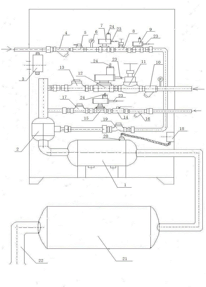
[0021] like figure 1 As shown, a pulse dust removal device includes a gas pipeline, a working air pipeline, a purge air pipeline and a pulse generating pipeline, and the pulse generating pipeline includes a first connecting pipe, a mixing tank 2, a second connecting pipe in sequence Pipe, ignition tank 1, third connecting pipe, pulse tank 21 and pulse nozzle 22, the gas pipeline is connected to the mixing tank 2 and can be communicated through a switch; the working air pipeline and purge air pipeline They are respectively connected to the pipe wall of the first connecting pipe, and can be switched and communicated by a changeover switch. A high-energy igniter 18 is also included, and the high-energy igniter 18 is c...


PUM


Abstract

The invention relates to a pulse dust collection device. The pulse dust collection device comprises a fuel gas pipeline, a working air pipeline, a purging air pipeline and a pulse generation pipeline, wherein the pulse generation pipeline sequentially comprises a first connecting pipe, a mixing tank, a second connecting pipe, an ignition tank, a third connecting pipe, a pulse tank and a pulse nozzle; the fuel gas pipeline is connected and communicated with the mixing tank; the working air pipeline and the purging air pipeline are respectively connected and communicated with the pipe wall of the first connecting pipe. Since the mixing tank is arranged on the pulse generation pipeline, the fuel gas pipeline is connected and communicated with the mixing tank; the working air pipeline and the purging air pipeline are respectively connected and communicated with the pipe wall of the first connecting pipe, by firstly feeding working air and purging air into the first connecting pipe at the front end of the mixing tank and directly feeding fuel gas into the mixing tank, the working air, the purging air and the fuel gas can be uniformly mixed through the mixing tank, the ignition efficiency of the ignition tank is greatly improved and the equipment stability is improved.

Description

technical field [0001] The invention relates to a pulse dust removal device, which belongs to the field of gas conveying equipment. Background technique [0002] The gas and air control device of the existing gas high-energy pulse ash removal device, the gas pipeline, the working air pipeline and the purge air pipeline are all directly connected to the ignition tank in the pulse generating pipeline, and the gas mixing in this structure is uneven , ignition effect. Another kind of defect is to use general electromagnetic valve to switch the gas for miners. Because the closing force of this electromagnetic valve is small, it is easy to leak, and the explosion-proof ability is weak, and the sealing gasket is easy to damage and needs to be replaced frequently. Large losses are caused, and the equipment cannot operate normally. Contents of the invention [0003] The technical problem to be solved by the present invention is to provide a pulse dust removal device, which overco...

Claims


Application Information

Patent Timeline
IPC IPC(8): F23J1/00F23J3/00B08B5/02
Inventor 陈勇
Owner CHONGQING KEZHONG MACHINERY
Why Eureka
Try Eureka