Method and device for controlling engine ignition system

A technology of an engine ignition system and a control method, which is applied in the field of control of the engine ignition system, and can solve problems such as detonation, incomplete distribution of control devices, and undisclosed details

Inactive Publication Date: 2011-11-09
KYMCO
View PDF9 Cites 3 Cited by
  • Summary
  • Abstract
  • Description
  • Claims
  • Application Information

AI Technical Summary

Problems solved by technology

[0007] Although the ignition control method disclosed in the aforementioned invention patents not only detects the engine speed signal, but also further detects engine load information (such as engine manifold pressure, throttle opening, etc.) to determine the best ignition angle. The aforementioned invention patents do not further disclose the relationship between the engine speed, manifold pressure, or throttle opening, nor do they disclose in detail the ignition angle determined under what conditions are the engine speed, manifold pressure, or throttle opening? Therefore, although the aforementioned patents suggest that information such as engine speed, manifold pressure, or throttle opening can be simultaneously detected to determine the optimal ignition angle, thereby improving ignition efficiency, the specific technical means are lacking.
[0008] As mentioned above, when the ignition spark of the engine is weak or the ignition timing is inaccurate, the engine will be weak, fuel consumption, knocking, and a large amount of exhaust gas will be emitted, which not only wastes energy, but also affects the quality of the environment
[0009] From the above, it can be seen that the control device of the existing engine ignition system is still not fully developed, and needs to be further reviewed and improved, and to seek a feasible solution

Method used


Image

  • Method and device for controlling engine ignition system
  • Method and device for controlling engine ignition system
  • Method and device for controlling engine ignition system

Examples


Embodiment Construction

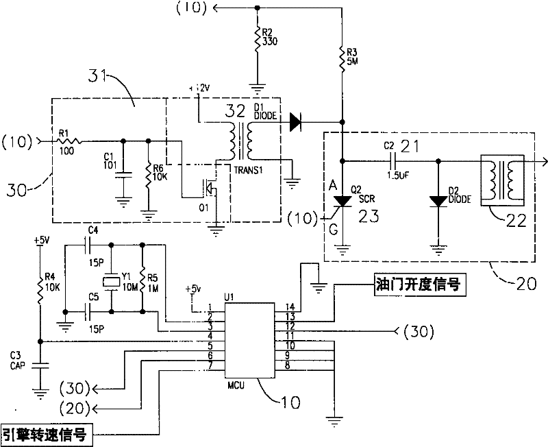
[0024] see figure 1 As shown, the specific circuit structure of the feasible embodiment of the control device of the present invention is disclosed, which is mainly composed of a control unit (10), a capacitive discharge ignition unit (20) and a charging voltage supply unit (30); wherein:

[0025] The capacitive discharge ignition unit (20) is mainly composed of a capacitor (21), an ignition coil (22) and an electronic switch (23), wherein one end of the capacitor (21) is connected to the charging voltage supply unit (30) by the electronic switch (23) The output terminal is connected, and the other end of the capacitor (21) is connected to the ignition coil (22); The output terminal of the voltage supply unit (30) is connected, and its grid G ​​is connected with the output terminal of the control unit (10), and the output signal of the control unit (10) is received to control whether it is turned on or not, and then determines whether the capacitor (21) is Discharges the ign...


PUM


Abstract

The invention relates to a method and a device for controlling an engine ignition system. A control unit simultaneously receives an engine rotating speed signal and a throttle opening signal and crosswise judges whether the signals are higher than or lower than a set value; when different judging conditions are satisfied, ignition voltage is raised or lowered, so that voltage is increased for ignition on the conditions of low speed and high fuel quantity and voltage is lowered for ignition on the conditions of high speed and low fuel quantity. By the adoption of the adaptive control technology provided by the invention, the purposes of full burning, improvement in ignition efficiency, power saving, energy saving, carbon emission reduction and the like can be achieved.

Description

technical field [0001] The invention relates to a control method and device for an engine ignition system, in particular to a related technology that can adaptively adjust the ignition voltage with the change of the rotational speed and the size of the fuel supply. Background technique [0002] General engines use high-voltage electric sparks to ignite the mixed gas for operation. The aforementioned ignition system mainly uses thousands of volts of high-voltage electricity to jump over the electrode gap of the spark plug to generate sparks, and ignites the compressed mixed gas to form a flame core. Then quickly expand to the entire combustion chamber to produce rapid combustion, make the gas expand rapidly, and push the piston to generate power. [0003] According to the experiment, when the maximum pressure is generated in the cylinder, the position of the crankshaft is about 15° before the top dead center, and the engine can get the maximum power. The compression ratio, g...

Claims


Application Information

Patent Timeline
Patent Type & Authority Applications(China)
IPC IPC(8): F02P5/15F02D43/00
Inventor 谢世甲郭永吉吕坤郎
Owner KYMCO
Why Eureka
Try Eureka