
Continuous output positioning control method

A technology of positioning control and speed, applied in the direction of control using feedback, etc., can solve problems such as inability to adjust control parameters, failure of positioning function, no adaptive control function, etc., and achieve the effect of improving debugging efficiency

Inactive Publication Date: 2008-11-26
SHANGHAI BAOSIGHT SOFTWARE CO LTD
View PDF0 Cites 9 Cited by
  • Summary
  • Abstract
  • Description
  • Claims
  • Application Information

AI Technical Summary

Problems solved by technology

[0004] In addition, because there is no adaptive control function, when the equipment parameters change, such as friction resistance or inertia changes, the control parameters cannot be adjusted accordingly, and the system cannot always be in the best control state
[0005] In addition, when there is a position drift caused by mechanical leakage, once the position deviation exceeds the allowable value, it will cause the failure of the final positioning function

Method used


Image

  • Continuous output positioning control method
  • Continuous output positioning control method
  • Continuous output positioning control method

Examples


Embodiment Construction

[0014] The present invention will be described in further detail below in conjunction with the accompanying drawings and embodiments.

[0015] The present invention provides a method of continuous output positioning control, which requires the actuator of positioning control to have a stepless and continuously adjustable output, such as a speed-regulating motor or a proportional valve, and also requires a detection device for the actual position of the equipment. In order to determine the "opening and closing" movement direction of the equipment during control, the polarity of the detection device for the actual position must be defined, and its requirements are as follows figure 2 As shown, that is, when the device moves in the "open" direction, the actual value of the detected position is required to become larger. When moving in the "closed" direction, the detected position actual value is required to be smaller.

[0016] 1. A new speed curve algorithm

[0017] exist fi...


PUM


Abstract

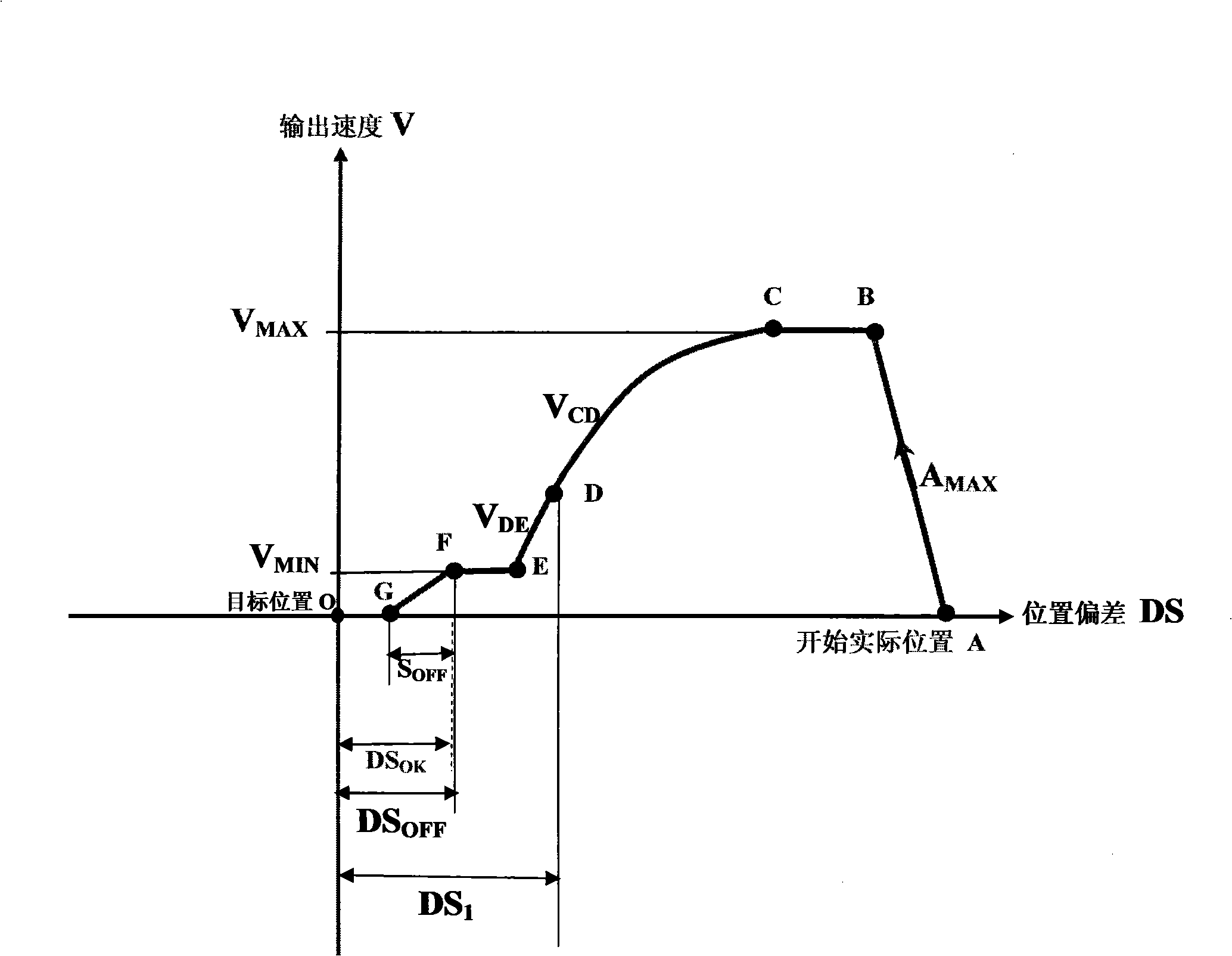
The present invention discloses a continuous output positioning control method. At the beginning, the maximum acceleration speed AMAX of equipment allowed is increased to the maximum allowed speed VMAX; the equipment is closed at the point C, the speed is reduced to VCD; when the equipment moves to the point D, and the position deviation distance value is DS1, the speed keeps on reducing to VDE; when the equipment moves to the point E, the speed is shifted into the minimum speed VMIN; when the equipment moves at the point F, and the position deviation distance value is DSOFF, the speed output is switched off, and the equipment keeps on moving under the inertia effect and stops moving at the point G. The present invention discloses a novel calculation method of speed curves VCD and VDE and has high positioning control precision and the shortest movement time for arriving at the target position; the present invention discloses the method of automatically obtaining control parameters DS1, VMIN and DSOFF; the present invention also discloses the method of the self-adaptation control on the parameter DSOFF and the following control function of the positioning control.

Description

technical field [0001] The invention relates to a positioning control method for equipment with continuous output capability, and is especially suitable for application in metallurgical plants. Background technique [0002] The positioning control requirements of equipment widely exist in metallurgical plants. Such as the control of the height of the steel coil of the entrance steel coil trolley rising to the center height of the uncoiler, the width positioning control of the steel coil inserted into the uncoiler, etc. The actuators used here for positioning control are continuously adjustable proportional valves or speed-regulating motors, which can be continuously adjusted steplessly in two moving directions. Continuous output positioning control process such as figure 1 As shown, the device is at point A at the beginning, and the device is required to locate to the target position O. At the beginning the device starts with the highest allowed acceleration A MAX Rise t...

Claims


Application Information

Patent Timeline
IPC IPC(8): G05D3/20B21C47/16
Inventor 王育华
Owner SHANGHAI BAOSIGHT SOFTWARE CO LTD
Learn More