
Fully mechanized caving face along-track end bracket

A technology of fully mechanized caving face and end bracket, applied in the field of end bracket of fully mechanized caving face, can solve the problems of difficult column replacement, inability to adjust spacing, inability to bear eccentric load, etc., so as to improve supporting capacity and supporting area, Simple structure and good adaptability

Inactive Publication Date: 2008-12-03
兖矿能源集团股份有限公司
View PDF1 Cites 14 Cited by
  • Summary
  • Abstract
  • Description
  • Claims
  • Application Information

AI Technical Summary

Problems solved by technology

[0004] In order to overcome the disadvantages that the anchoring bracket of the existing rail-side end bracket of the fully mechanized caving face is not easy to change the column underground and cannot bear unbalanced loads, and the distance between the bases of the inner and outer frames of the leading bracket cannot be adjusted, and further improve the supporting capacity of the entire bracket and Stability, the present invention provides a new end support for rail alignment of fully mechanized caving working face, its anchoring support is convenient to change uprights underground, can bear partial load, the distance between the bases of the inner and outer frames can be adjusted, and the force of the support The structure is more reasonable, and the supporting capacity of the bracket is greatly improved

Method used


Image

  • Fully mechanized caving face along-track end bracket
  • Fully mechanized caving face along-track end bracket

Examples


Embodiment Construction

[0026] The present invention will be further described below in conjunction with drawings and embodiments.

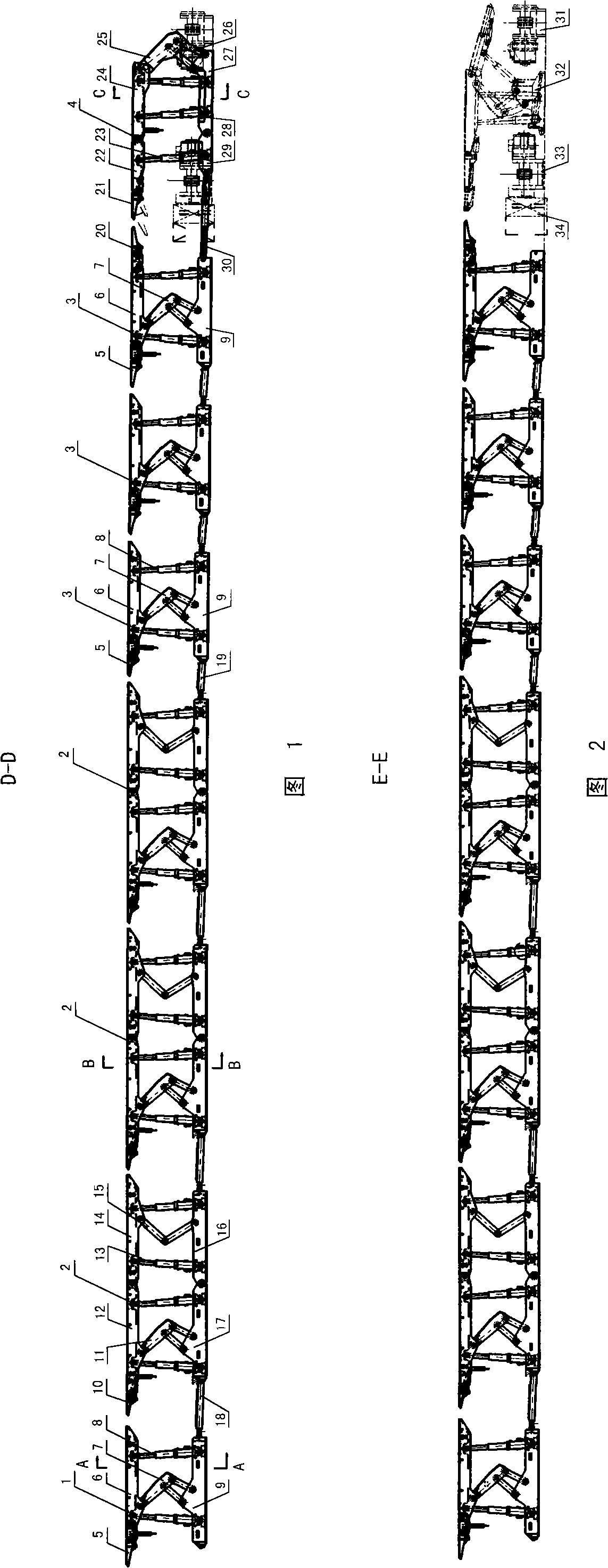
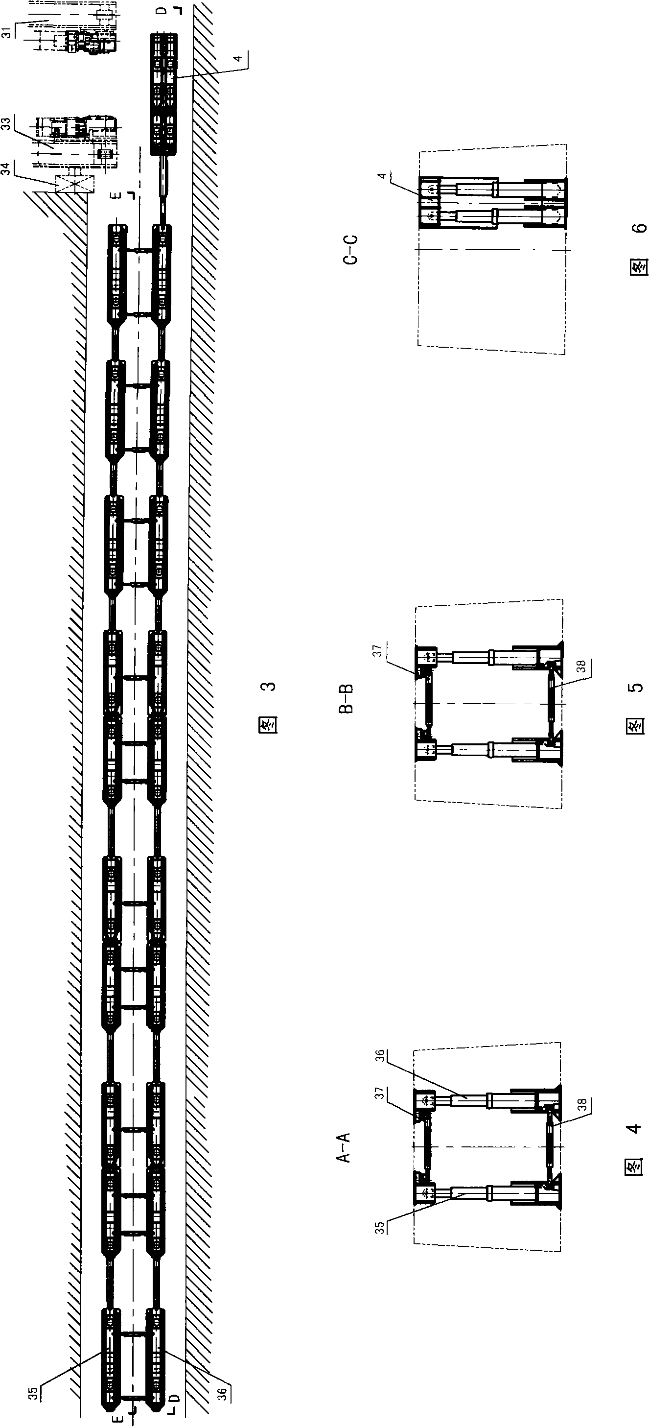
[0027] Figures 1 to 3 show the composition of the rail alignment end bracket of the fully mechanized caving face of the present invention. Its support structure is a four-frame eight-combination type; along the advancing direction of the working face, it is composed of anchor brackets 1, three sets of advanced brackets 2, three sets of end brackets 3, and tail brackets 4. The eight sets of brackets are sequentially connected to the whole end bracket of the cost rail through the pulling jacks between the bases.

[0028] ①Anchor bracket 1: It is a four-column and four-link structure with two inner and outer frames; that is, the anchor bracket 1 is composed of an inner frame 35 and an outer frame 36, that is, the top beam and the base are both inner and outer parts. All between the top beam 6 and the base 9 of the inner and outer frames are formed by two front and rear co...


PUM


Abstract

A face-end support for the track channel of a fully-mechanized caving face is composed of an anchor support (1), a fore support (2), a face-end support (3), and a tail-end support (4). The anchor support has a four-pillar and four-connection-rod structure and includes an internal and an external supports, wherein both the internal and the external supports are composed of a top beam, a pedestal, two pillars and a four-connection-rod mechanisms. The fore support includes 3 to 5 groups, and each group has an eight-pillar structure and includes an internal and an external supports, wherein both the internal and the external supports are composed of a hinged top beam, a hinged pedestal, four pillars, a four-connection-rod and single-swing-rod mechanism, and a forepoling beam. The face-end support includes 1 to 3 groups, and each group has a four-pillar and four-connection-rod structure and includes an internal and an external supports. The tail-end support has a six-pillar hinge beam structure. An adjusting jack is arranged between the top beams of the internal and the external supports and the pedestal of each support. The face-end support solves the problems that the anchor support has difficulty in changing the pillars and is not easy to bear offset loads and that the distance between pedestals of the internal and the external supports is not easy to be adjusted. Accordingly, the face-end support has more reasonable force bearing capacity, and can improve the support ability and the stability of the support. Two kinds of step pitch moving supports reduce repeatedly supporting. The face-end support is suitable for channels with large pressure and large deformation along hollow tracks.

Description

technical field [0001] The invention relates to an end bracket of a fully mechanized caving face, in particular to a rail end support of a fully mechanized caving face suitable for the end support of the track along the groove of the mechanized caving face and the advance support. Background technique [0002] At present, the end support of the fully mechanized caving face and the advanced support of the level road generally adopt the traditional intensive support method of "cross" top beam or "one-shaped beam" combined with a single hydraulic prop. This method is slow and efficient. Low cost, large number of employees, high labor intensity and poor work safety. It does not match with the modern fully mechanized caving equipment and becomes a weak link and "bottleneck" in the development of fully mechanized top coal caving mining technology. The end of the track in the fully mechanized caving face, especially the end of the track along the empty track, due to the large infl...

Claims


Application Information

Patent Timeline
IPC IPC(8): E21D23/04E21D23/16
Inventor 倪兴华李政马晓东李纪栋张崇宏蒲宝山谢波张善波祝炳梁赵琪苗丽华
Owner 兖矿能源集团股份有限公司
Learn More