Device operable to distribute driving forces

A driving force and distributed technology, which is applied to the transmission device, differential transmission device, control device, etc., can solve the problem that the left and right driving wheels cannot be suppressed from slipping, and achieve the effect of compact structure and improved driving stability

Inactive Publication Date: 2008-12-03
MITSUBISHI MOTORS CORP
View PDF1 Cites 7 Cited by
  • Summary
  • Abstract
  • Description
  • Claims
  • Application Information

AI Technical Summary

Problems solved by technology

[0005] As a result, a problem arises that the slippage of the left and right drive wheels cannot be suppressed when the vehicle is running straight
[0006] If the slippage of the left and right driving wheels is suppressed by the technology of Japanese Patent No. 2,738,225 when the vehicle is running straight, such as the driving force is switched to the left wheel or the right wheel, there is a problem with the steering of the vehicle

Method used


Image

  • Device operable to distribute driving forces
  • Device operable to distribute driving forces
  • Device operable to distribute driving forces

Examples


Embodiment Construction

[0036] Typical embodiments of the present invention will be described below with reference to the accompanying drawings.

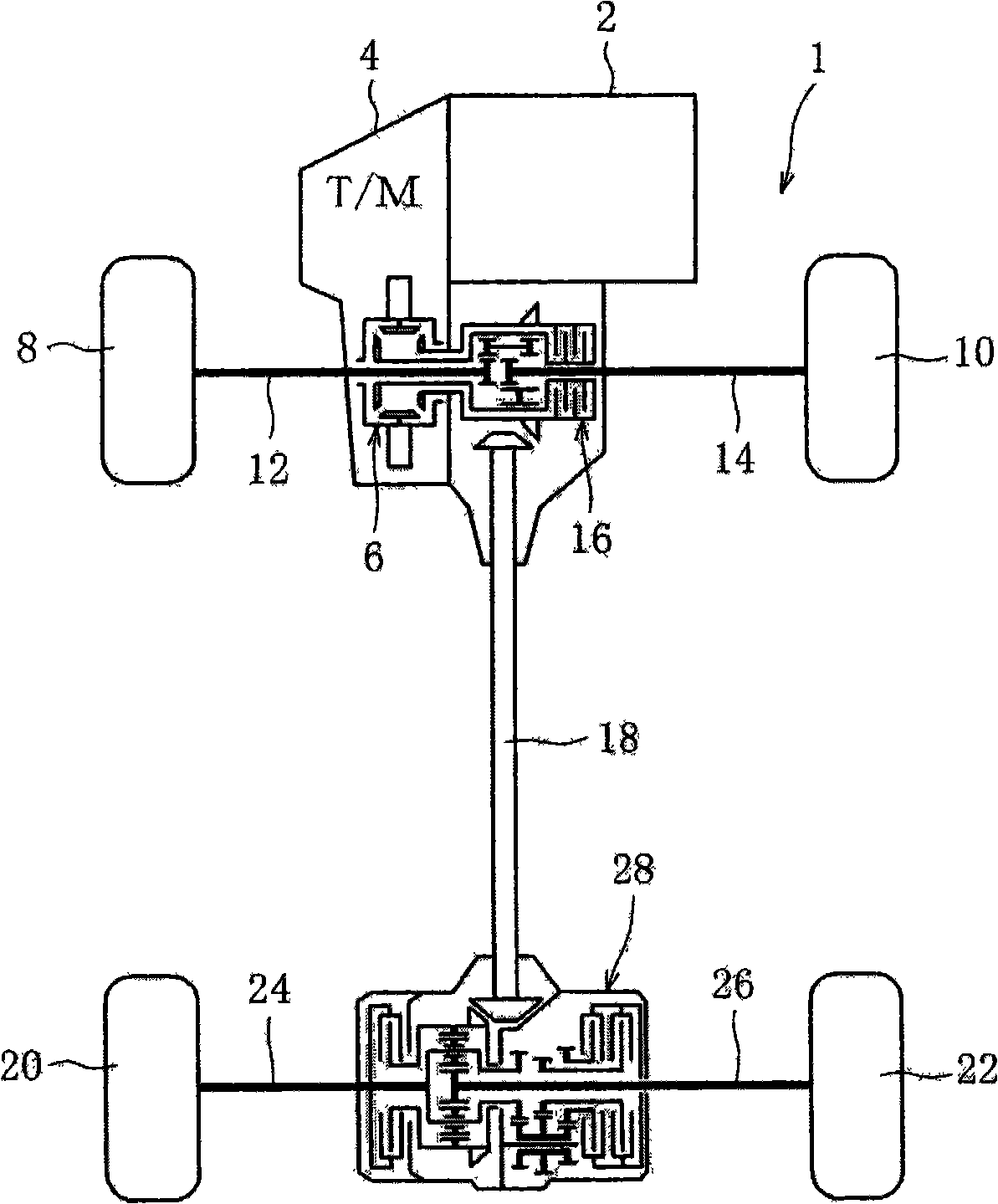
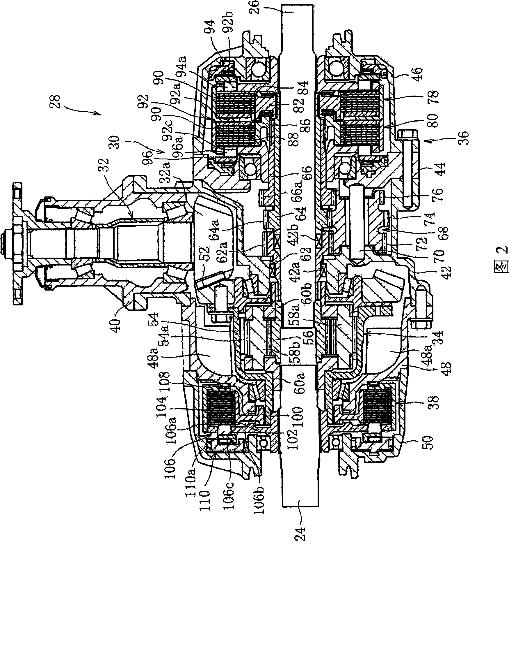
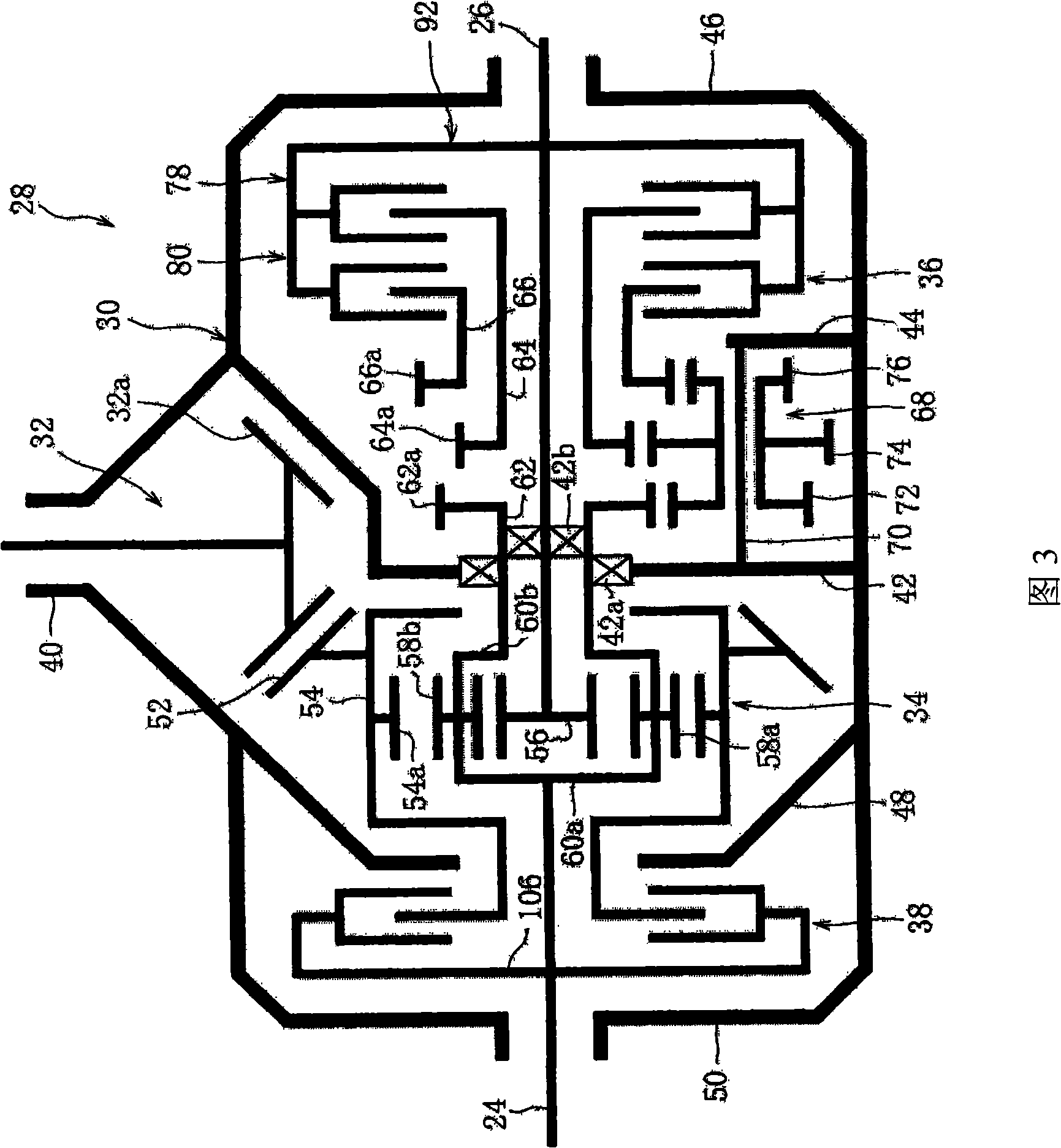
[0037] according to Figure 1 to Figure 4 ,in figure 1 It is a complete structural diagram of a vehicle with a drive force lateral distribution device according to the present invention; Fig. 2 is a sectional view of the drive force lateral distribution device according to the present invention; accompanying drawing 3 is a structural schematic diagram of the drive force lateral distribution device according to the present invention ; Figure 4 is a perspective view of the left partition in the drive force lateral distribution device according to the present invention.

[0038] Such as figure 1 As shown, the vehicle 1 is a four-wheel drive vehicle, and the structure includes: an engine 2 installed on the front of the vehicle body as a driving source; a transmission 4 connected to one side of the engine 2; connected to the transmission 4 to distribute the...


PUM


Abstract

A device operable to distribute driving forces to left and right wheels of a vehicle, includes: a differential mechanism, a driving-force adjuster and a differential limiter. The differential mechanism is operable to distribute a driving force from a drive sourceof the vehicle to the left and right wheels as distributed driving forces, while allowing a rotation difference between the left and right wheels. The driving-force adjuster is operable to adjust each of the distributed driving forces. The differential limiter is operable to limit rotation difference between the left and right wheels by applying a limiting torque to the differential mechanism.

Description

technical field [0001] The present invention relates to a driving force lateral distribution device, and more particularly, the present invention relates to a technique for appropriately distributing driving force generated by a driving force source such as an engine to left and right wheels according to a running state of a vehicle. Background technique [0002] In recent years, an apparatus for controlling the yaw moment acting on the vehicle, which generates a driving force difference between the left and right wheels when the vehicle turns, thereby improving the steering performance of the vehicle, has been developed. [0003] For example, Japanese Patent No. 2,738,225 discloses a driving force lateral distribution device with a driving force transmission control mechanism, which distributes the driving force on the left and right wheels by transmitting the driving force of the engine from the input unit, and simultaneously transmits the driving force on the left and righ...

Claims


Application Information

Patent Timeline
Patent Type & Authority Applications(China)
IPC IPC(8): F16H48/22B60K23/04F16H48/30F16H48/32F16H48/36F16H48/38
CPCF16H48/36F16H48/22F16H2048/423F16H2048/368F16H2048/204F16H48/10B60K23/04F16H48/30F16H48/08
Inventor 山村卓也后田祐一泽濑薰
Owner MITSUBISHI MOTORS CORP
Why Eureka
Try Eureka