
Double-column horizontal rotation type high-voltage isolation switch

A high-voltage isolating switch, horizontal rotary technology, applied in the direction of air switch parts, switches with movable electrical contacts, etc. Reliability and safety, the effect of reducing the lateral impact force

Inactive Publication Date: 2008-12-03
闫淼江
View PDF2 Cites 13 Cited by
  • Summary
  • Abstract
  • Description
  • Claims
  • Application Information

AI Technical Summary

Problems solved by technology

This problem can sometimes cause serious damage, such as breaking post insulators and similar accidents, reducing the reliability and safety of equipment
However, it is actually very difficult to solve this problem by simply enlarging post insulators on high-current and high-voltage disconnectors, so that the above-mentioned technical solution of "(High-voltage disconnector contact assembly" cannot fully play its technical role.

Method used


Image

  • Double-column horizontal rotation type high-voltage isolation switch
  • Double-column horizontal rotation type high-voltage isolation switch
  • Double-column horizontal rotation type high-voltage isolation switch

Examples


Embodiment 1

[0038] Embodiment 1: as attached figure 1 , 2 , 3, and 4 show:

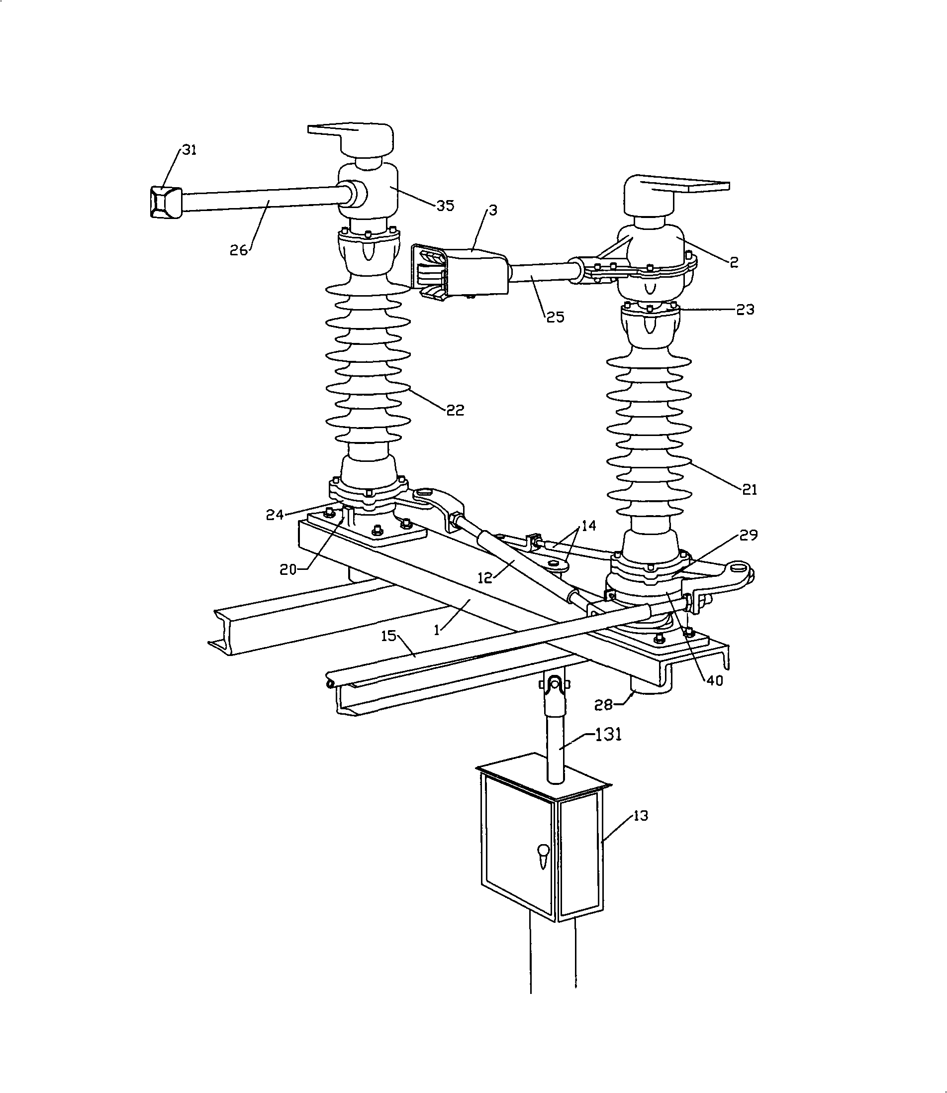
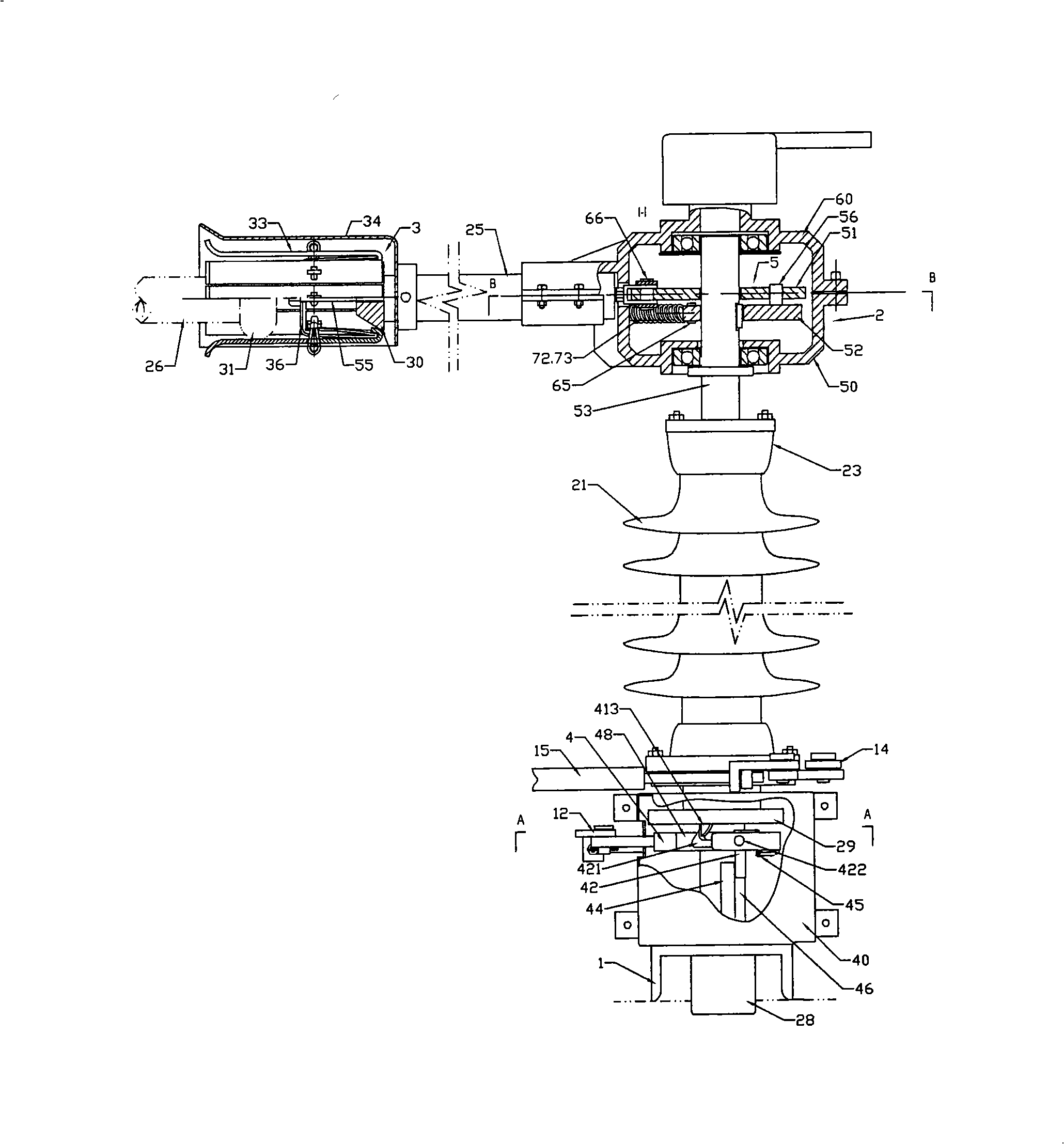
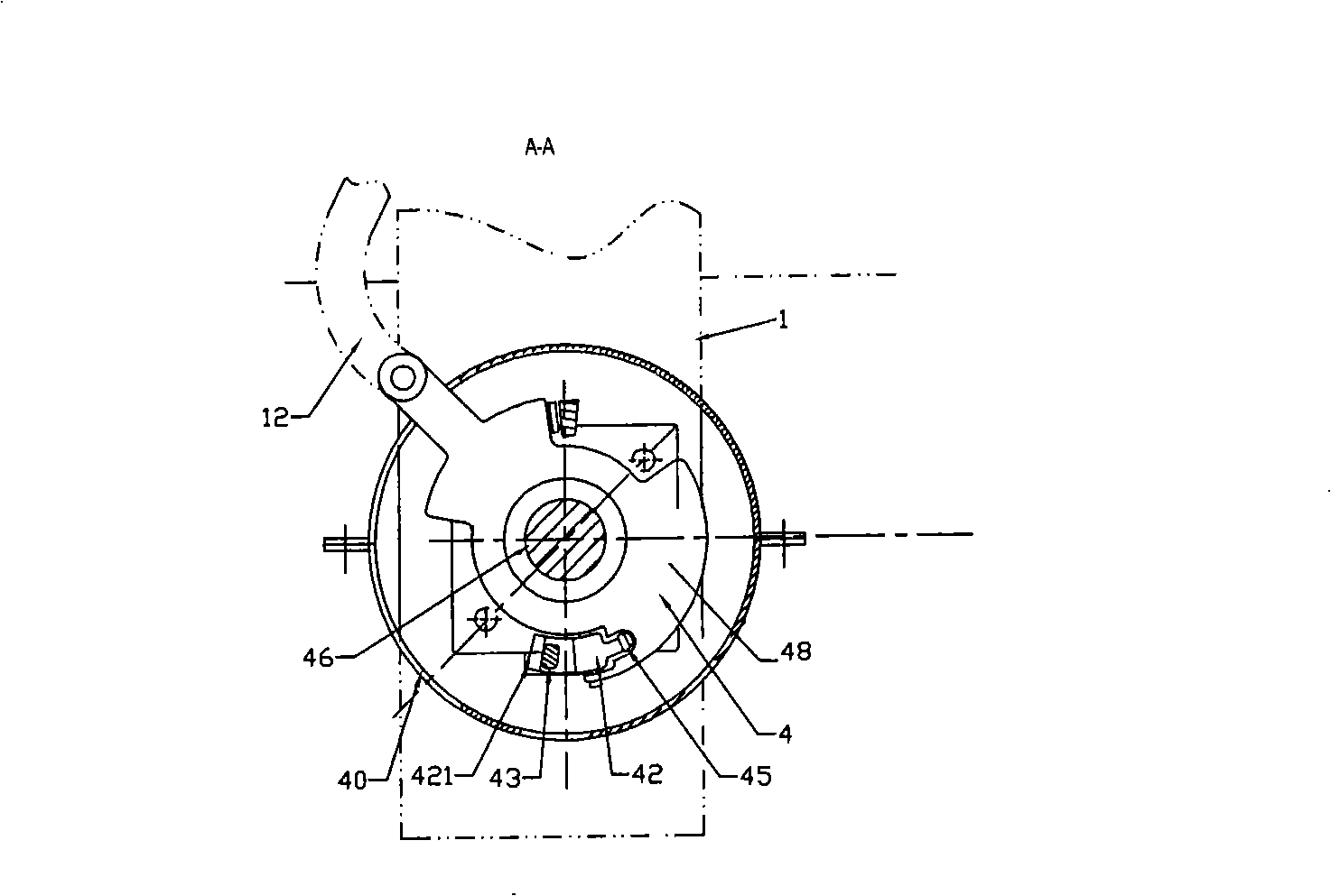
[0039] In this embodiment, the present invention includes the active side post insulator 21 and the driven side post insulator 22 supported on the base 1; Flange 29 is hinged with a transmission pull rod 14 that is connected with operating mechanism 13 in the prior art; Flange 29 is integrally connected with a shaft 46, and a limit tripping device 4 is arranged on the flange shaft 46, and the limit tripping The device 4 is rotatably supported on the flange shaft 46, and a transposition transmission mechanism 2 is arranged between the active side post insulator 21 and the conductive arm 25. The transposition transmission mechanism 2 includes a transmission assembly 5, a transposition clutch 7. The flange shaft 53 and the casing 50. The casing 50 of the transposition transmission mechanism 2 is rotatably supported on the flange shaft 53, and the flange shaft 53 is flange-fixed with the post insulator 21. The she...

Embodiment 2

[0044] Embodiment 2: as shown in accompanying drawing 5,6,7:

[0045] In this example, if Figure 7 As shown, the limit tripping device 4 includes a tripping wheel 48 and a tripper 41 provided on it, and the tripper 41 is provided with a tripping rod 412 that can move upwards, and a spring 415 Cooperate with the upper end of the tripping rod 412 to provide a buckle 413 under the lower flange 29, and cooperate with the lower end of the tripping rod 412 to provide a tripping guide rail 411 on the base 1.

[0046] In this embodiment, the transposition transmission mechanism 2 includes a transmission assembly 5, a transposition clutch 7 housing 50 and a flange shaft 53, and the transmission assembly 5 is provided with a transmission plate 58, a cam 59 and a transmission rod, There is a long hole 582 in the middle of the transmission plate 58 along the direction of the transmission rod to pass through the flange shaft 53. The lower side of the transmission plate 58 is provided wit...

Embodiment 3

[0050] Embodiment 3: as shown in the accompanying drawing Figure 8 shown.

[0051] In this embodiment, the transposition transmission mechanism 2 includes a transmission assembly 5, a transposition clutch 7, a flange shaft 53 and a housing 50, and the transmission assembly 5 includes a drive plate 62, a transmission plate 61, and a transmission rod 55 , the transmission plate 61 has a long slot 611 parallel to the transmission rod, and a long slot 612 perpendicular to the transmission rod is formed on the side of the transmission plate away from the transmission rod. The flange shaft 53 runs through the long slot 611, and on the drive plate The edge of 62 is provided with a push rod 621 in the vertical direction, the flange shaft 53 is fixedly connected with the drive plate 62, the drive plate 61 is fixedly connected with the drive rod 55, and the drive plate 62 is passed through the long groove 612 by the set push rod 621. The frictional fit transforms the torque into the l...


PUM


Abstract

The invention relates to a dual-column horizontal rotation type high-voltage isolation switch, which is a switch device for isolating a powered device and a power-off device in a power system; the dual-column horizontal rotation type high-voltage isolation switch comprises two post insulators which are supported on a base and a cross pull rod which is arranged between the two post insulators, and is characterized in that the dual-column horizontal rotation type high-voltage isolation switch further comprises a position changing transmission mechanism which is supported on a flange shaft at the top part of the post insulator at the driving side, the transposition transmission mechanism is connected with a main contact by penetrating a conductive arm by a transmission rod; a position limiting trip is supported on the flange shaft at the lower end of the post insulator at the driving side, and the position limiting trip is hinged with the cross pull rod. The dual-column horizontal rotation type high-voltage isolation switch realizes that the opening and closing operation of the high-voltage isolation switch is completed by two steps, thus effectively lowering the transverse impact which is generated at the instant of the opening and closing operation of the isolation switch and further improving the overall reliability and the safety of the isolation switch.

Description

Technical field: [0001] The invention relates to a double-column horizontal rotary high-voltage isolating switch, which is a switchgear for isolating electrified equipment and power-off equipment in a power system. Background technique: [0002] The high-voltage isolating switch is a switching device used in the power system to separate and close the circuit with voltage and no load. On the open point, the high-voltage isolating switch can reliably pass the normal working current and withstand the short-circuit fault current in the closed state. In addition, the cooperation between the high-voltage isolating switch and the high-voltage switch can also change the load operation mode of the power grid. High-voltage isolating switch is the most used power equipment in the power system, and most of them are used outdoors [0003] In the existing equipment technology, take GW4 or GW14 disconnector as an example, they all include at least one phase switch body and an operating me...

Claims


Application Information

Patent Timeline
IPC IPC(8): H01H31/02H01H31/28
Inventor 闫淼江
Owner 闫淼江
Learn More