Open-end spinning rotor for textile machine producing cross-wound packages

A cross-winding bobbin and free-end technology, which is applied to the continuous winding spinning machine, free-end spinning machine, spinning machine, etc., can solve the problem of unfavorable control technology for the positioning of the spinning rotor and achieve the minimum moment of inertia effect of uniformity, load uniformity, and simplified actuation

Active Publication Date: 2008-12-03
SAURER GERMANY GMBH & CO KG
View PDF3 Cites 6 Cited by
  • Summary
  • Abstract
  • Description
  • Claims
  • Application Information

AI Technical Summary

Problems solved by technology

However, especially in such magnetically arranged spinning rotors, if the center of gravity of the spinning rotor is arranged too close to the area of ​​one of the bearing points (in this

Method used


Image

  • Open-end spinning rotor for textile machine producing cross-wound packages
  • Open-end spinning rotor for textile machine producing cross-wound packages
  • Open-end spinning rotor for textile machine producing cross-wound packages

Examples


Example Embodiment

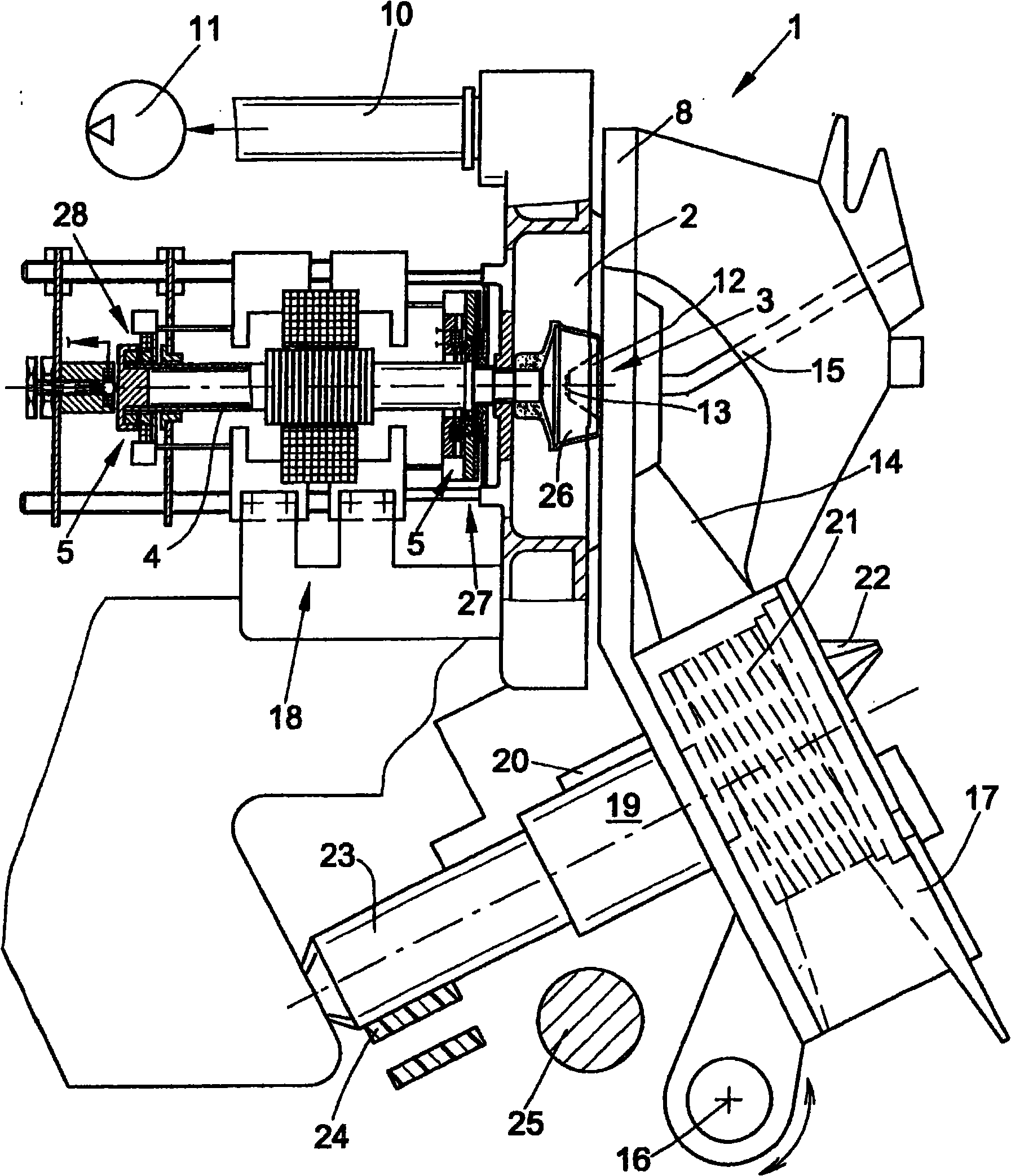
[0024] figure 1 An open-end spinning device 1 is shown with a spinning rotor 3 magnetically mounted and driven by a separate motor.

[0025] An open-end spinning device 1 of this type is known and described in relatively detail, for example, in EP 0 972 868 A2. Each of these open-end spinning devices 1 has a rotor housing 2 in which the spinning rotor 26 of the spinning rotor 3 rotates at high speed.

[0026] In the present example, the spinning rotor 3 is preferably driven by a separate electric motor drive 18 and is supported by its rotor shaft 4 on the front bearing point 27 and the rear bearing point 28 of the magnetic bearing structure 5, both bearing points radially The spinning rotor 3 is positioned upward again in the axial direction.

[0027] The rotor hood 2 , which itself is open to the front, is closed during the spinning operation via a pivotably mounted cover part 8 and is connected via a corresponding pneumatic line 10 to a source of negative pressure 11 , whi...


PUM

PropertyMeasurementUnit
Wall thicknessaaaaaaaaaa

Abstract

The invention concerns an open-end spinning rotor for a textile machine producing cross-wound packages, comprising a rotor shaft(4) mounted rotatably via a magnetic bearing assembly and also a rotor cup (26) comprising a front-side rotor opening, a fibre slip wall (31) emanating from the rotor opening, a so-called rotor groove (33a) and also a rotor bottom (6) with a moulded-on connecting collar (7), the rotor cup (3) being connectable to the rotor shaft (4), via a connector (9) fixable in the connecting collar (7), to be nonrotating and if desired easily releasable. The invention provides that the rotor cup (26) is fabricated as a thin wall structure and formed such that the centre of gravity of the rotor cup (26) is disposed in a region (50B, 50D) which, viewed from the rotor opening (30), is behind the fibre slip wall (31).

Description

technical field [0001] The invention relates to an open-end spinning rotor for a spinning machine for producing cross-wound bobbins, which has the features of the preamble of claim 1 . Background technique [0002] An open-end spinning rotor of this type is known, for example, from EP 1 156 142 B1. In these spinning machines producing cross-wound bobbins, the rotor shafts of the spinning rotors are respectively located in magnetic bearing structures to support the spinning rotors, and said spinning rotors are driven by separate motors. The magnetic bearing structures of these spinning machines respectively include a front support point and a rear support point, and these two support points have axially opposite permanent magnetic rings. One of the two permanent magnet rings is fixed to the stator, the other permanent magnet ring rotates with the rotor shaft of the spinning rotor. [0003] The installation or disassembly of the rotor shafts of spinning rotors mounted in thi...

Claims


Application Information

Patent Timeline
IPC IPC(8): D01H4/10
CPCD01H4/10
Inventor 海因茨-格奥尔格·瓦森霍芬布丽吉特·里德
Owner SAURER GERMANY GMBH & CO KG
Why Eureka
Try Eureka