Heat recovering device

A heat recovery device and heat technology, applied in indirect heat exchangers, heat exchanger types, lighting and heating equipment, etc., can solve the problem of lowering the internal temperature of the firing furnace, reduce thermal insulation materials, and improve heat recovery efficiency. , the effect of reducing manufacturing costs

Active Publication Date: 2008-12-10
KOYO THERMO SYST CO LTD
View PDF3 Cites 6 Cited by
  • Summary
  • Abstract
  • Description
  • Claims
  • Application Information

AI Technical Summary

Problems solved by technology

However, ventilation will lower the internal temperature of the firing furnace

Method used


Image

  • Heat recovering device
  • Heat recovering device

Examples


Embodiment Construction

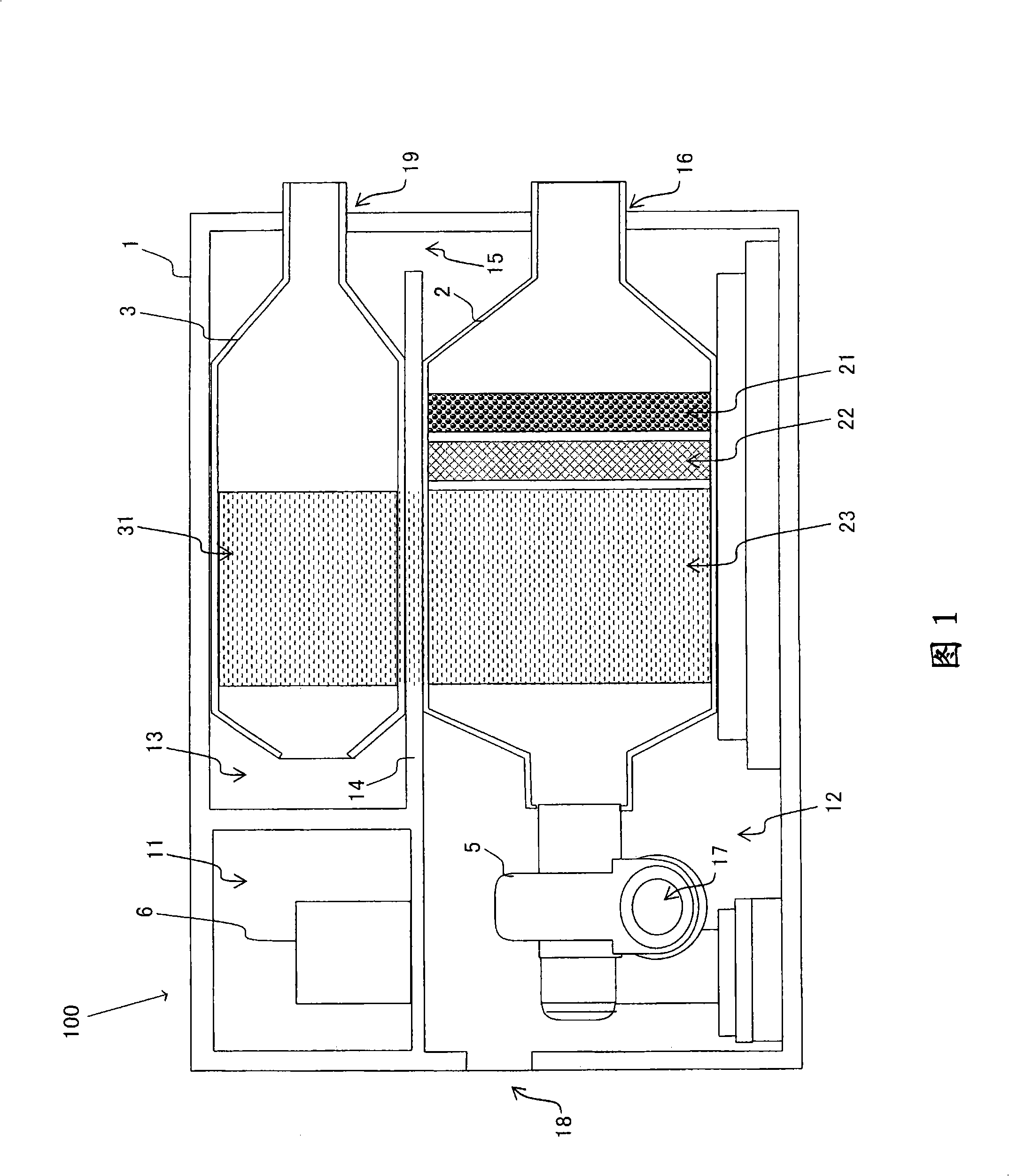
[0015] Hereinafter, a structural example of the heat recovery device will be described with reference to the drawings. The heat recovery device here is used to ventilate the multi-stage firing furnace used in the manufacturing process of liquid crystal display panels. The exhaust gas from the multi-stage kiln contains organic components generated by the evaporation of binders and the like. The heat recovery device discharges the waste gas to the outside of the furnace and draws fresh air into the furnace.

[0016] Fig. 1 is a side sectional view of a heat recovery device. Shown in the figure is a heat recovery device 100 of a fixed configuration. In addition, moving rollers or the like may be provided on the bottom surface of the heat recovery device 100 to move the heat recovery device 100 .

[0017] The heat recovery device 100 has an outer casing 1 . The interior of the outer casing 1 is divided into a control chamber 11 , a main preheating chamber 12 and a secondary pr...


PUM


Abstract

The invention provides a heat recovery device. Compared with the prior heat recovery device, the heat recovery device can improve heat recovery efficiency and control manufacturing costs at the same time. The heat recovery device (100) comprises a heat exchange unit (4), a main preheating chamber (12) and a secondary preheating chamber (13). The main preheating chamber (12) is provided with a high temperature chamber (2). The secondary preheating chamber (13) is provided with a low temperature chamber (3). The heat exchange unit (4) recovers heat from the high temperature chamber (2) and emits the recovered heat to the low temperature chamber (3). The secondary preheating chamber (13) is positioned at the front section of the low temperature chamber (3) in a passage of low temperature gases, and the main preheating chamber (12) is positioned at the front section of the secondary preheating chamber (13) in the passage of low temperature gases. In the main preheating chamber (12), the low temperature gases suck the heat emitted from the high temperature chamber (2).

Description

technical field [0001] The invention relates to a heat recovery device for recovering the heat of high-temperature gas to heat low-temperature gas. Background technique [0002] Firing furnaces are used in the process of manufacturing liquid crystal display panels, etc. In the firing furnace, the gas evaporated from the workpiece often contains the vapor of organic matter. This vapor may adversely affect workpieces. Therefore, it is necessary to ventilate the furnace in the firing furnace. Ventilation, however, lowers the internal temperature of the firing furnace. Therefore, heat exchange is required between the exhaust gas from the furnace and the suction gas fed into the furnace. [0003] The device (for example, with reference to Japanese Invention Patent Laid-Open Publication 2002-191920, Japanese Patent Laid-Open Publication 2001-154739, and Japanese Patent Laid-Open Publication Laid-Open 2001-154739 to heat low-temperature gas is known. 2002-200473). [0004] Ho...

Claims


Application Information

Patent Timeline
Patent Type & Authority Applications(China)
IPC IPC(8): F23L15/00F23J15/06
CPCY02P10/25F28D7/00F28D15/00
Inventor 长岛靖佐佐木泰浩
Owner KOYO THERMO SYST CO LTD
Why Eureka
Try Eureka