Rotary heat engine
A technology of heat engine and rotating shaft, applied in the direction of rotary piston engine, rotating or swinging piston engine, engine components, etc., can solve problems such as temperature difference, achieve the effects of increased contact area, high retention, and reduced heat loss
- Summary
- Abstract
- Description
- Claims
- Application Information
AI Technical Summary
Problems solved by technology
Method used
Image
Examples
Embodiment 1
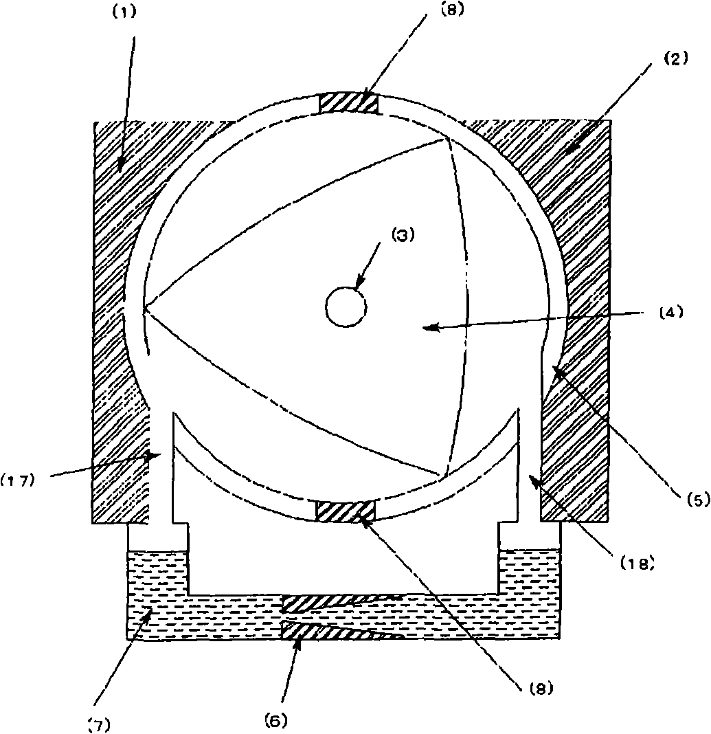
[0027] figure 1 It is a view schematically showing the configuration of main parts of an embodiment of the rotary heat engine according to the present invention, which will be described below with reference to the accompanying drawings. The rotary heat engine of Embodiment 1 has a substantially triangular rotor 4 rotatably provided inside a cylinder, and a heat receiving part 1 and a heat releasing part 2 are mounted integrally or in contact with the outer periphery of the cylinder 5 . Furthermore, in order to thermally insulate between the heat receiving part 1 and the heat releasing part 2, a heat insulating material 8 is sandwiched between the cylinder walls on the heat receiving part side and the heat releasing part side, thereby forming the cylinder wall in the middle part. In addition, in this embodiment, although a substantially triangular rotor is used, as long as it is an example rotor that can ensure a space for storing vaporized gas, it is not particularly limited t...
Embodiment 2
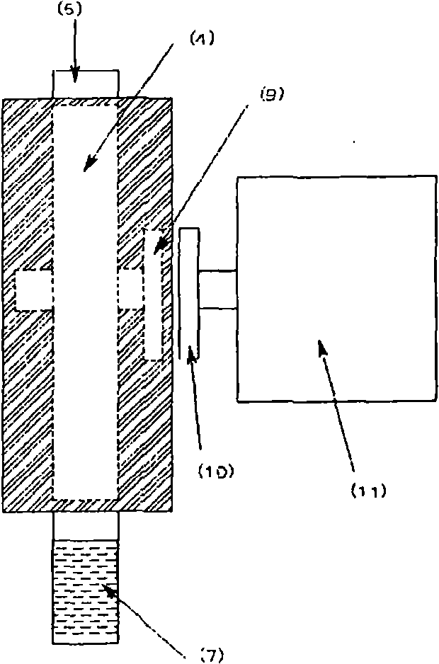
[0033] figure 2 is a side view of Embodiment 2, which shows the outline of combining an external generator with the heat engine of Embodiment 1. The following description will also be made with reference to the drawings. figure 2 The symbols 4, 5, 7 and figure 1 Similarly, the rotor, cylinder and working fluid reservoir are shown respectively. Also, 9 shows a permanent magnet installed on the rotating shaft 3 of the rotor, which is magnetically connected with a permanent magnet 10 installed on the input shaft of the generator 11 and can rotate with each other without contact. For this reason, by sealing the permanent magnet 9 attached to the rotating shaft 3 of the rotor in the casing provided on the cylinder 5, leakage of the working fluid and / or gas from the cylinder 5 can be completely prevented. In addition, the connection between the rotating shaft of the rotor and an external device such as a generator is not limited to the non-contact connection using magnetic forc...
Embodiment 3
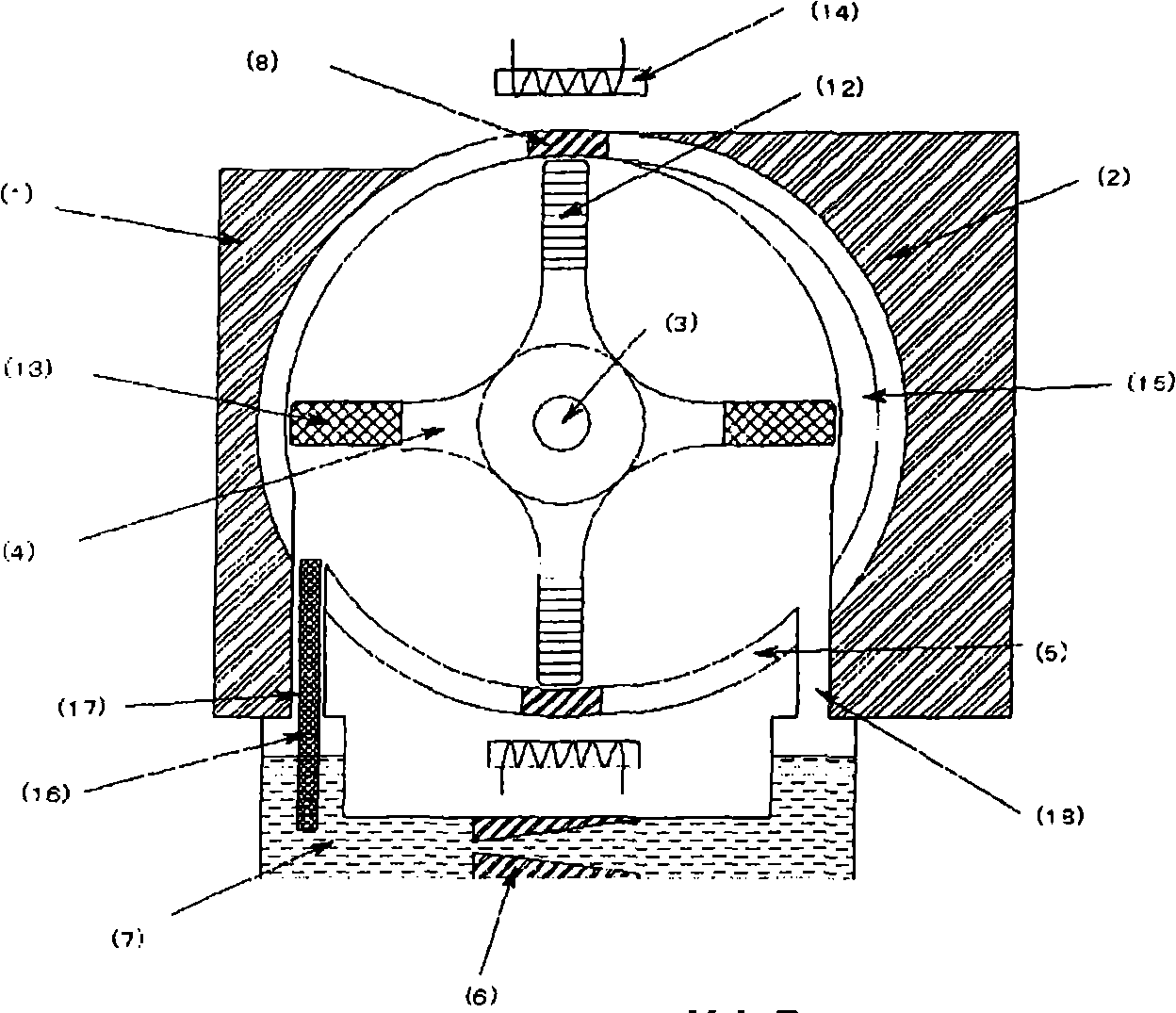
[0036] like image 3 The shown embodiment 3 is the power generation system of the rotary heat engine of the present invention, which is equipped with a capillary tube 16 arranged in the vaporized gas supply circuit 17 connecting the heat receiving part 1 and the working fluid storage part 7, and connecting the heat releasing part 2 The inner wall surface of the cylinder 5 is equipped with fins 15 for heat exchange extending approximately perpendicularly from the inner wall surface of the cylinder toward the rotating shaft 3 of the rotor to improve the output of the rotary heat engine; The polarities of the adjacent magnets are S poles and N poles arranged alternately to arrange permanent magnets 12, 13 with different polarities, and the magnetic force of the permanent magnets 12, 13 is outside the rotation area of the rotor 4. A structure in which the coil 14 for generating electricity is arranged in the area and can generate electricity by itself. In addition, although fin...
PUM
 Abstract
Description
Claims
Application Information
 - R&D
- Intellectual Property
- Life Sciences
- Materials
- Tech Scout
- Unparalleled Data Quality
- Higher Quality Content
- 60% Fewer Hallucinations
Browse by: Latest US Patents, China's latest patents, Technical Efficacy Thesaurus, Application Domain, Technology Topic, Popular Technical Reports.
© 2025 PatSnap. All rights reserved.Legal|Privacy policy|Modern Slavery Act Transparency Statement|Sitemap|About US| Contact US: help@patsnap.com


