
Speaker

A technology of loudspeaker and magnetic circuit, applied in the field of loudspeakers, can solve the problems of soft diaphragm and easy transmission, and achieve the effect of simple structure

Inactive Publication Date: 2008-12-10
MINEBEA CO LTD
View PDF2 Cites 54 Cited by
  • Summary
  • Abstract
  • Description
  • Claims
  • Application Information

AI Technical Summary

Problems solved by technology

[0009] Although the above two speakers are constructed to effectively dissipate the heat generated in the voice coil, the diaphragm is directly connected to the bobbin, therefore, there is still the problem that the heat is easily transferred to the diaphragm, thereby softening the diaphragm

Method used


Image

  • Speaker
  • Speaker
  • Speaker

Examples


Embodiment approach

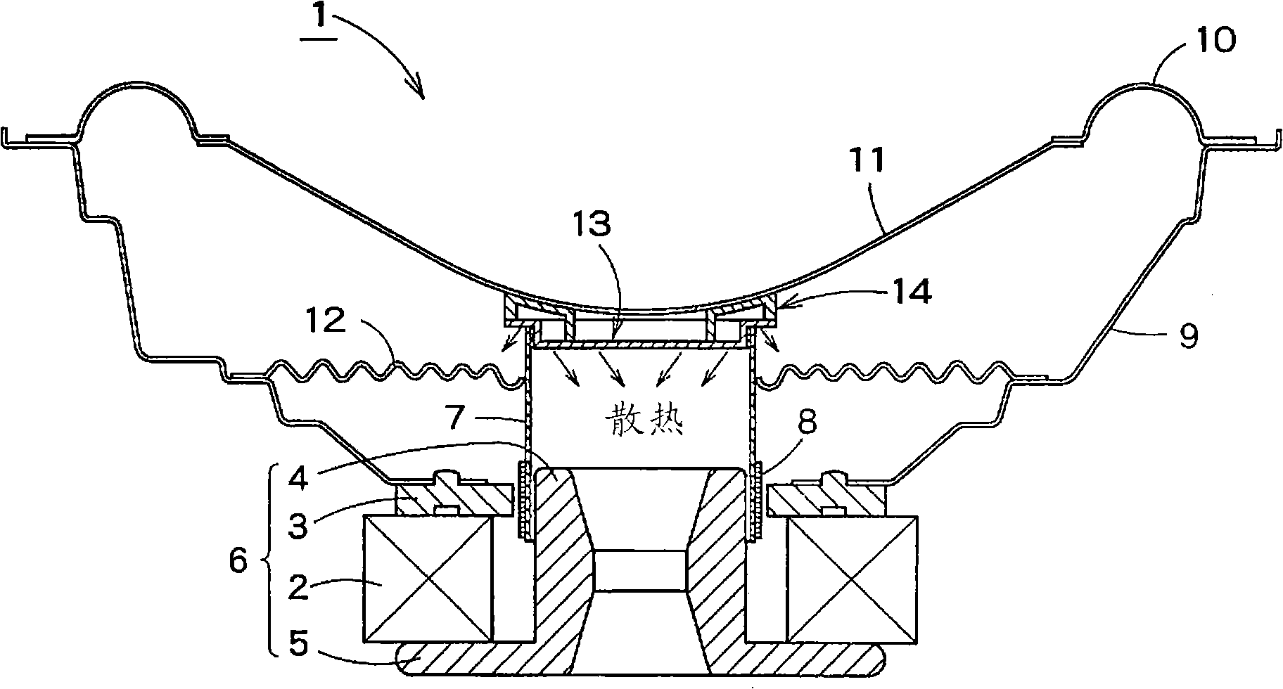
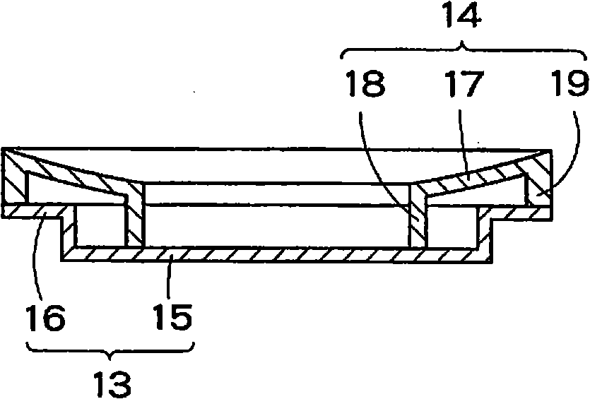
[0034] The following will refer to figure 1 with 2 The first embodiment of the present invention will be described. refer to figure 1 , The loudspeaker 1 according to the first embodiment includes: an outer magnetic circuit 6 composed of a ring magnet 2, a top plate 3 having a ring shape and disposed on the front surface of the magnet 2, a center pole 4 disposed through the magnet 2, and a central pole 4 disposed in the center It consists of a yoke 5 with a central pole 4; a bobbin 7 which surrounds a part of the magnetic circuit 6; a voice coil 8 which is wound around the bobbin 7 and is set in the magnetic gap of the magnetic circuit 6 and is suitable for front and rear movement; a basket 9, which is connected to the magnetic circuit 6; a diaphragm 11, whose outer periphery is connected to the basket 9 via a surround 10; a support ring 12, whose inner periphery is connected to the bobbin 7, and whose The outer peripheral part is supported on the middle part of the basin...


PUM


Abstract

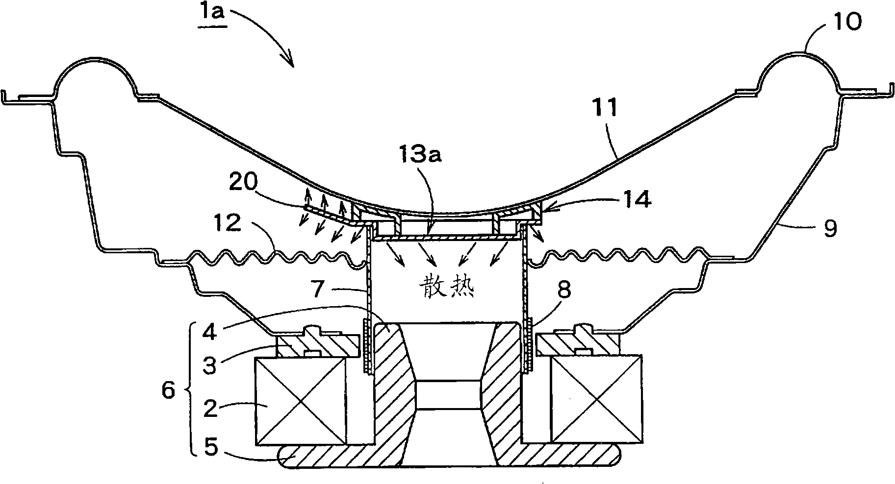
A speaker (1) includes: a heat sink (13) disposed at the front of a bobbin (7); and a coupler (14) disposed between the front of the heat sink (13) and the rear of a diaphragm (11), wherein the heat sink includes: a base portion (15) having an outer circumferential wall and disposed inside the bobbin (7); and a flange portion (16) extending axially outwardly from the forefront of the outer circumferential wall and having its rear face disposed in contact with the front of the bobbin (7), and the coupler includes: a diaphragm supporting portion (17) disposed at the rear of the diaphragm; and inner and outer annular walls disposed at the diaphragm supporting portion (17), and wherein the heat sink is connected to the coupler (14) such that the base portion and the flange portion of the heat sink are connected respectively to the inner annular wall (18) and the outer annular wall (19) of the coupler.

Description

technical field [0001] The present invention relates to speakers used in audio equipment, information and communication equipment, and the like. Background technique [0002] Figure 15 A generally conventional loudspeaker is shown. refer to Figure 15 , the conventional loudspeaker 100 includes: a magnetic circuit 105, which is mainly composed of a ring magnet 101, a top plate 102 having a ring shape and being arranged on the front surface of the magnet 101, a central pole (center) that passes through the central opening of the magnet 101 and the top plate 102 and is arranged. pole) 103, and a yoke 104 arranged on the rear surface of the magnet 101 and having a central pole 103 in the center; a bobbin 106, which is arranged to surround a part of the magnetic circuit 105; winding, set in the magnetic gap of the magnetic circuit 105, and adapted to move back and forth; a basket 108, which is connected to the magnetic circuit 105; a diaphragm 110, which is connected to the ba...

Claims


Application Information

Patent Timeline
Patent Type & Authority Applications(China)
IPC IPC(8): H04R9/02H04R9/06
CPCH04R9/022
Inventor 林繁
Owner MINEBEA CO LTD
Learn More