

LED Retrofit Lamp With a Strike Barrier
- Summary
- Abstract
- Description
- Claims
- Application Information
AI Technical Summary
Benefits of technology
Problems solved by technology
Method used
Image

Examples
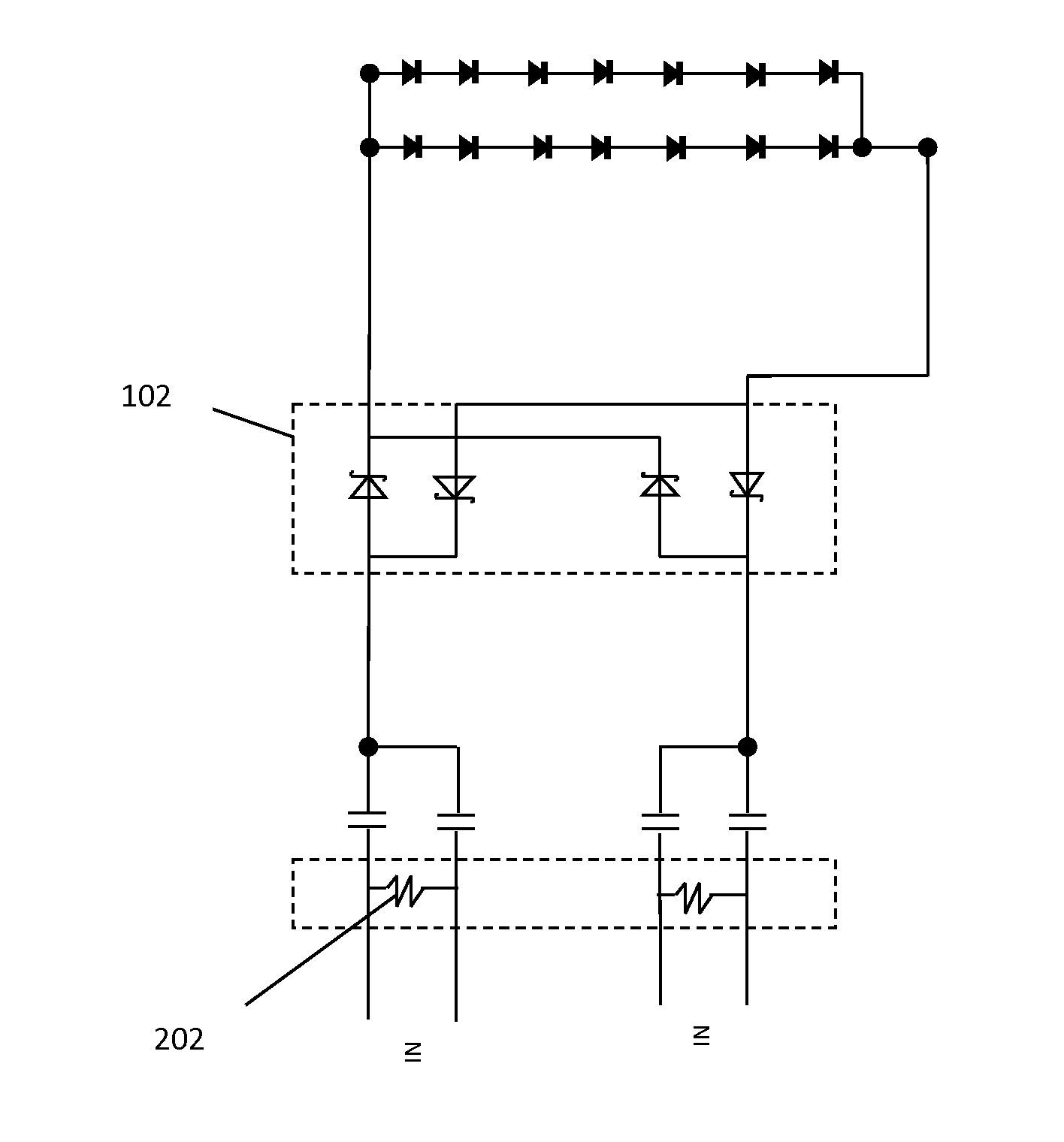
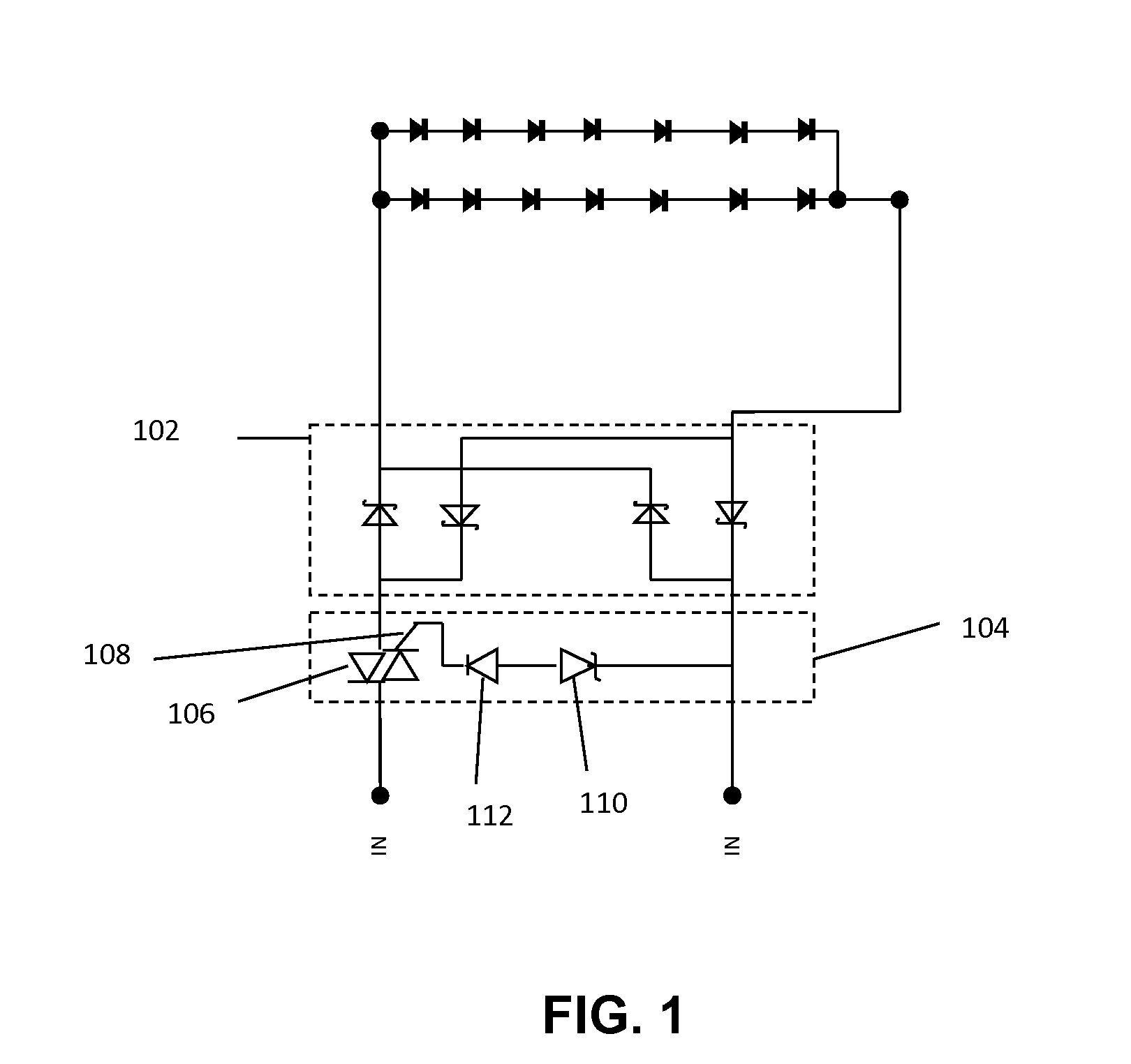
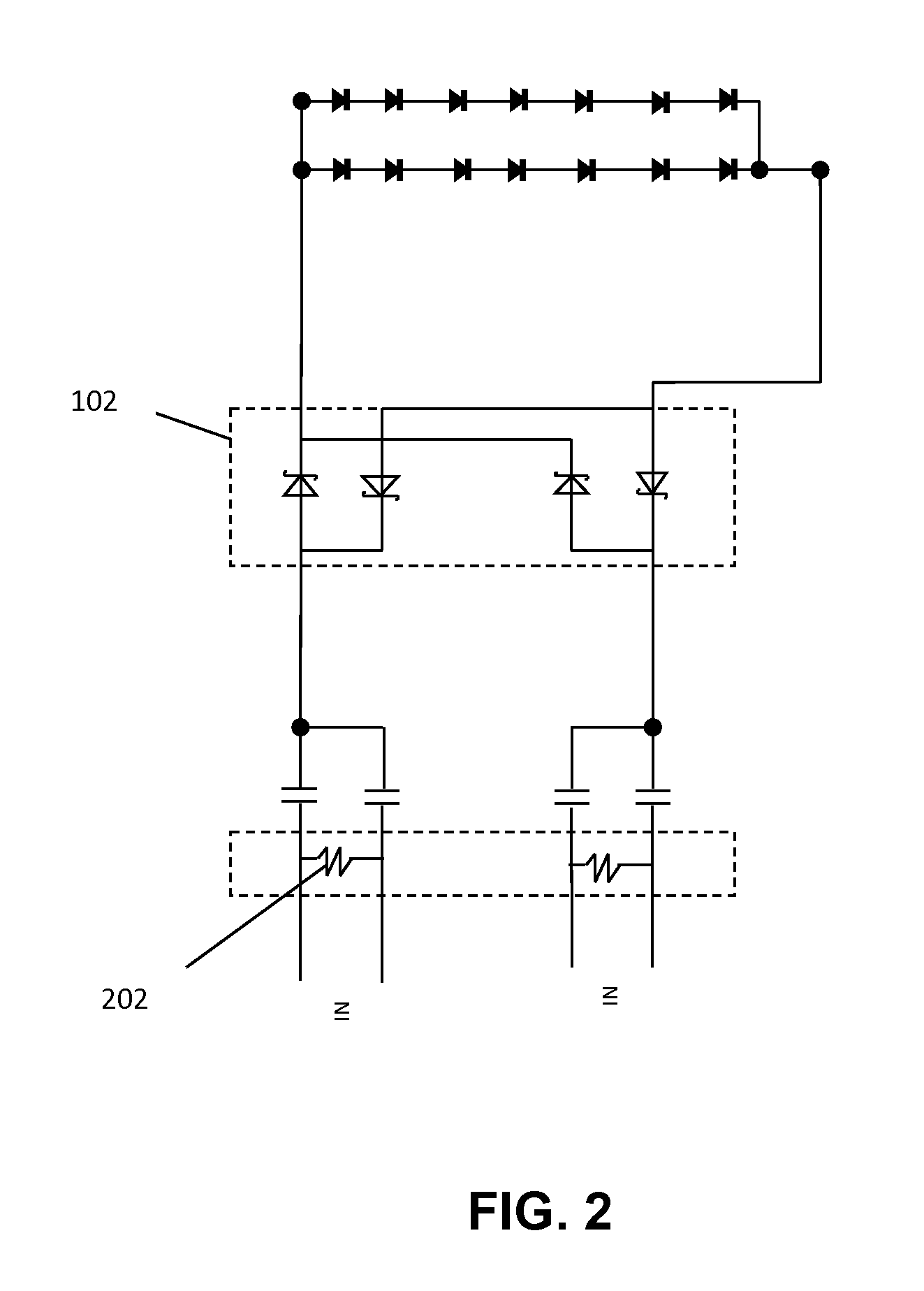
Embodiment Construction
[0010]In the following detailed description of embodiments of the invention, numerous specific details are set forth in order to provide a thorough understanding of the embodiment of invention. However, it will be obvious to a person skilled in art that the embodiments of invention may be practiced with or without these specific details. In other instances well known methods, procedures and components have not been described in details so as not to unnecessarily obscure aspects of the embodiments of the invention.
[0011]Furthermore, it will be clear that the invention is not limited to these embodiments only. Numerous modifications, changes, variations, substitutions and equivalents will be apparent to those skilled in the art, without parting from the spirit and scope of the invention.
[0012]In embodiments of the present invention, Rapid Start and Programmed Start Florescent ballasts preheat the cathodes prior to generating a high enough voltage to strike and arc along the length of ...
PUM
 Abstract
Description
Claims
Application Information