Smoke cyclic screening and dedusting method and apparatus

A filter and dust removal device, circulation filter technology, applied in the direction of separation methods, dispersed particle filtration, chemical instruments and methods, etc., to achieve the effects of low temperature resistance, high filtration efficiency, and high temperature resistance

Inactive Publication Date: 2008-12-17
苏忠
View PDF0 Cites 4 Cited by
  • Summary
  • Abstract
  • Description
  • Claims
  • Application Information

AI Technical Summary

Benefits of technology

In this new design for filters, there are two channels: one works with both negative pressures from an exhaust duct and another called the return passageway where filtered particles exit; while also having some components like a spiral wheel or disc inside them. These elements help remove larger debris without being affected by too much heat during operation. Overall, these technical feature enhances its performance over existing designs.

Problems solved by technology

This patented technical solution described in this patents involves different ways to remove particulate matter from exhaust streams containing various types of chemicals that can be dangerous when released directly onto human skin without causing damage. Existing techniques have limitations due to their work temperatures ranging between 200-450°C which may affect materials like cathode ray tubes (CRT) and lead wires found inside buildings. Additionally, current cleaning processes require multiple stages involving filtration, centrifugal separation, precipitation, and drying steps, leading to increased costs associated with maintenance operations and environmental concerns over time.

Method used


Image

  • Smoke cyclic screening and dedusting method and apparatus
  • Smoke cyclic screening and dedusting method and apparatus
  • Smoke cyclic screening and dedusting method and apparatus

Examples


Embodiment Construction

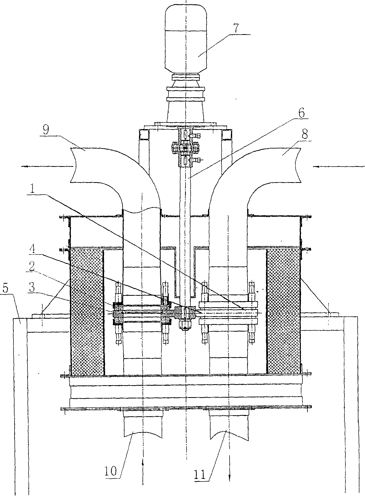
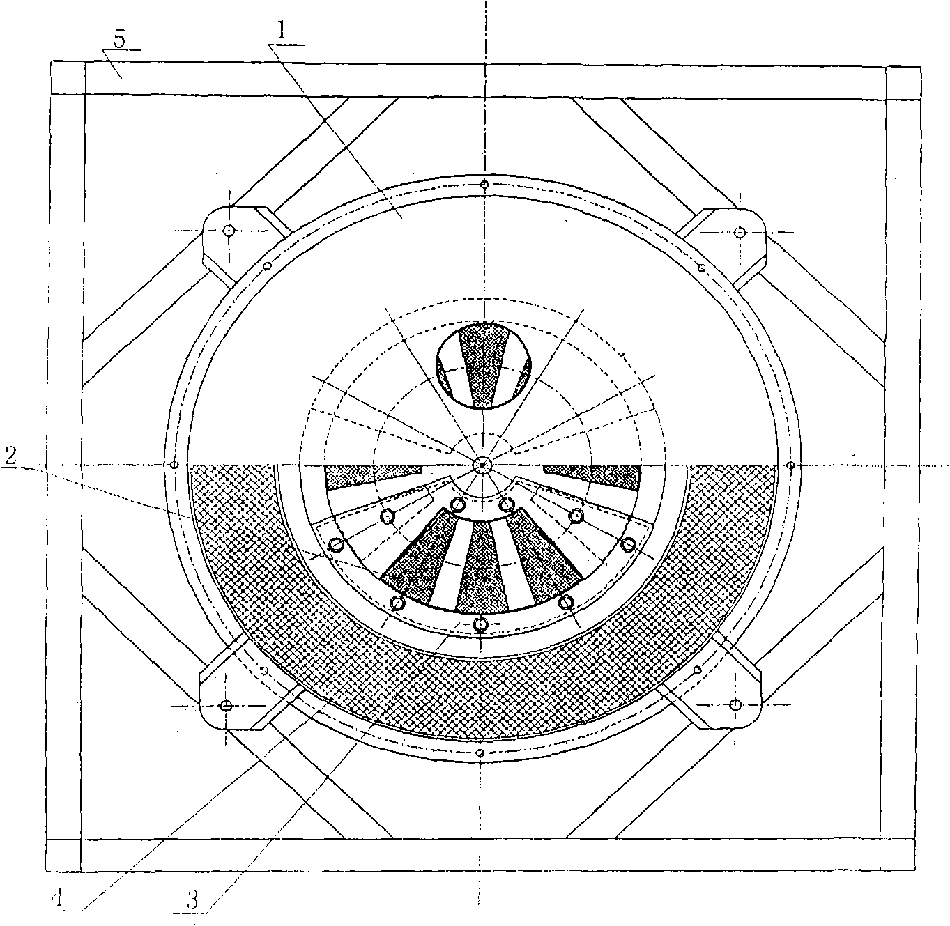
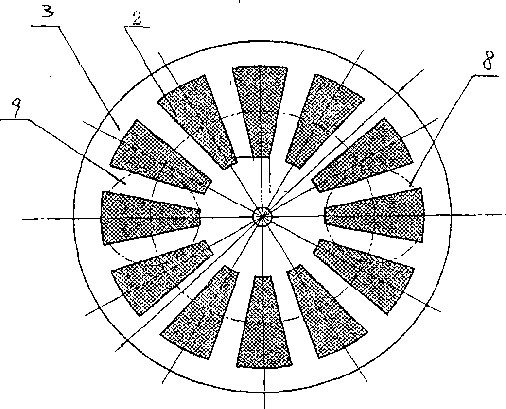
[0012] As shown in Figure 1, the filter and dust removal device body is composed of a filter mechanism 4, a drive motor 7, a dust discharge channel 9 and an airflow recoil channel 8, wherein the filter mechanism 4 is composed of a filter sieve disc 3 and a filter sieve 2 embedded thereon. composition (see image 3 ), and fixed on the frame 5, the middle part of the filter disc 3 is the rotating shaft 6 shaft connected in the sealed connection housing 1, and connected with the drive motor 7 to drive it to rotate, the connection housing 1 is set in the dust discharge On the cross section of the passage 9 and the airflow recoil passage 8, the flow direction of the recoil airflow and the discharge of smoke and dust is formed on the filter mechanism in the opposite direction. The dust discharge channel 9 and the airflow recoil channel 8 are distributed on the disk surface of the filter screen disc 3 with its axis symmetry (see figure 2 ), the flue gas is inhaled from the inlet 10...


PUM


Abstract

The invention discloses a circular soot filtering and removing method and a device thereof. A filter mechanism is a rotary disc structure which can rotate and a filter screen net is embedded on the rotary disc; the filter mechanism is arranged on the cross section of a soot emission channel and an airflow reverse channel of the soot removing device; the reverse airflow is opposite to the exhausted soot; then the soot is filtered and absorbed in the soot emission channel; when the rotary disc rotates from the position where the soot can be absorbed to the position of the airflow reverse channel, the reverse airflow can clean the position where the rotary disc can absorb the soot. At the moment, the position cleaned by the rotary disc rotates to the position soot emission channel to filter and absorb the soot; the process can be repeated and the cleaning of the position where the rotary disc can filter and absorb the soot can be automatically completed during the continuous rotating process. The circular soot filtering and removing method and the device can effectively clean and remove the soot in the warm gas with high temperature under the high temperature condition and complete the automatic cleaning of the filtering and rotary device.

Description


Claims


Application Information

Patent Timeline
Owner 苏忠
Why Eureka
Try Eureka