Three-arm type noncooperative target docking mechanism

A non-cooperative target and docking mechanism technology, applied in the field of satellite docking mechanism, can solve the problems of low docking success rate and extremely high motion precision requirements, and achieve the effect of improved reliability, low motion precision requirements, and high success rate

Active Publication Date: 2008-12-17
HARBIN INST OF TECH
View PDF0 Cites 38 Cited by
  • Summary
  • Abstract
  • Description
  • Claims
  • Application Information

AI Technical Summary

Problems solved by technology

[0003] The purpose of the present invention is to provide a three-arm non-cooperative target docking mechanism to solve the problem

Method used


Image

  • Three-arm type noncooperative target docking mechanism
  • Three-arm type noncooperative target docking mechanism
  • Three-arm type noncooperative target docking mechanism

Examples


specific Embodiment approach 1

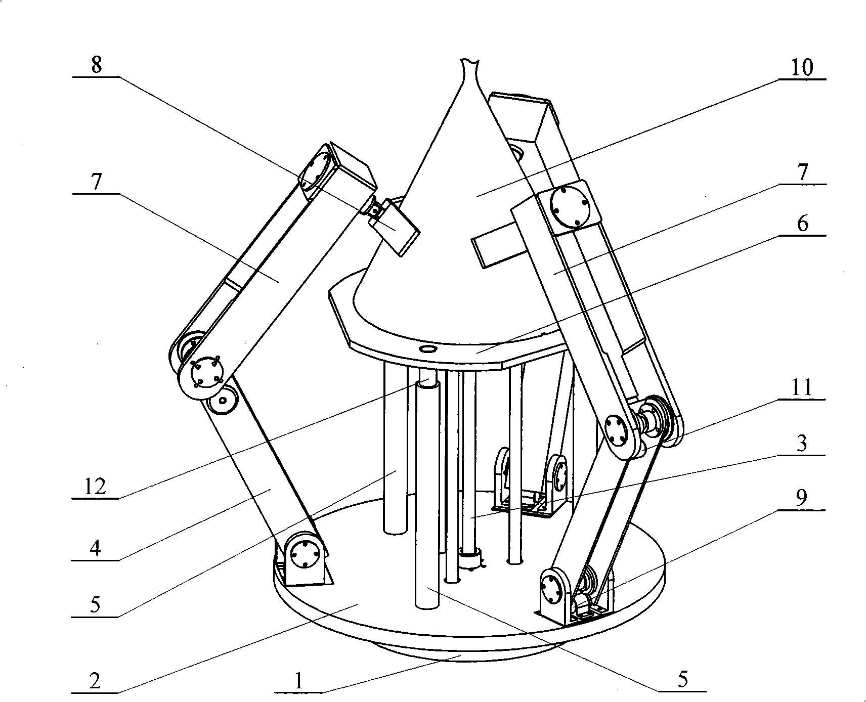
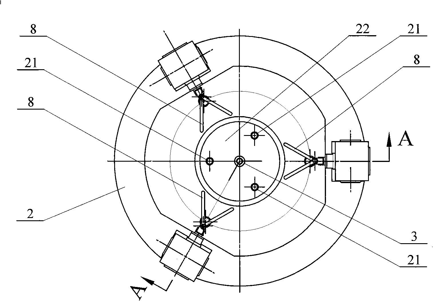
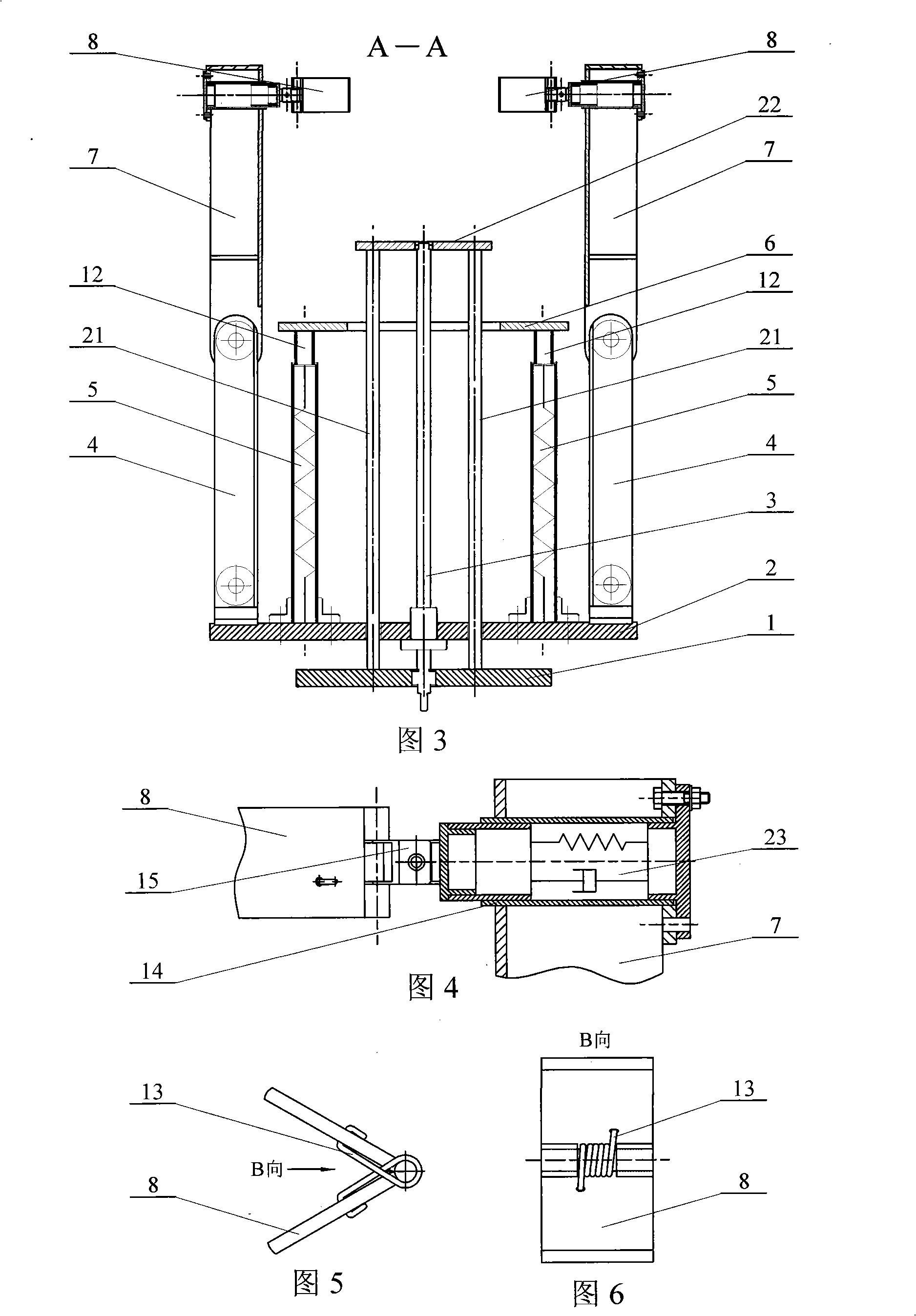
[0006] Specific implementation mode one: (see figure 1 ~ FIG. 6) This embodiment consists of a fixed platform 1, a support platform 2, a screw 3, three mechanical arms 4, three buffer columns 5, a target docking platform 6, three mechanical arms 7, and three ends Actuator, three No. 1 motors 9, three No. 2 motors 11, three buffer pistons 12, three slide rods 21 and a top plate 22. The fixed platform 1 is installed on the tracking satellite or other fixed planes. The fixed platform 1 is set On the lower side of the support platform 2, three mechanical arms 4 are arranged on the periphery of the support platform 2 at an angle of 120°, one end of the mechanical arm 4 is hinged with the support platform 2, and the other end of the mechanical arm 4 is connected to the One end of the small arm 7 of the mechanical arm is hinged, the other end of the small arm 7 of the mechanical arm is connected to the end effector, a No. 1 motor 9 is connected between the large arm 4 of each mechan...

specific Embodiment approach 2

[0007] Specific embodiment two: (referring to Fig. 3~Fig. 6) the end effector of this embodiment comprises hand claw 8, torsion spring 13, buffer bar 14 and Hooke hinge 15, and buffer bar 14 is fixed on the top end of mechanical arm forearm 7, One end of the Hooke hinge 15 is connected with the buffer rod 14, and the other end of the Hooke hinge 15 is connected with the claw 8, and the claw 8 is made up of two plates, and a torsion spring 13 is fixedly connected between the two plates. Other compositions and connections are the same as in the first embodiment.

specific Embodiment approach 3

[0008] Embodiment 3: (see FIG. 3 and FIG. 4 ) The end effector of this embodiment further includes a spring damper 23 , and the spring damper 23 is arranged between the buffer rod 14 and the forearm 7 of the mechanical arm. Other compositions and connections are the same as those in the second embodiment.

[0009] In the present invention, the end effector is composed of the claw 8, the torsion spring 13, the buffer rod 14 and the Hooke hinge 15. Because the small arm 7 of the mechanical arm is constantly moving closer to the nozzle 10 under the drive of the motor 11, after the claw 8 contacts the nozzle 10, and under the action of the contact force, the claw 8 gradually opens, and the two sides of the torsion spring 13 The two ends are respectively fixed on the two plates. As the opening of the claws 8 increases, the torque of the torsion spring 13 also increases. The clamping force makes the nozzle 10 press down on the target docking platform 6, the buffer piston 12 compres...


PUM


Abstract

The invention discloses a three-arm type non-cooperative target docking mechanism, relating to a satellite docking mechanism. The invention aims at solving the problems that the docking success rate of the existing satellite docking mechanism is comparatively low and the requirement on motion precision is extremely high. The three large mechanical arms of the invention are arranged on the periphery of a supporting platform at a 120 degree angle, one end of the large arm of the mechanical arm is articulated with the supporting platform, the other end thereof is articulated with one end of the small arm of the mechanical arm, and the other end of the small arm of the mechanical arm is connected with an end effector; the lower end of each bumper post is fixedly connected with the upper end of the supporting platform, the free end of each dashpot plunger is fixedly connected with the lower end of a target docking platform. In the invention, when the docking mechanism reaches a preset position, the three mechanical arms and the target docking platform form a closed region to encase a jet pipe, therefore, the jet pipe is placed in an inescapable space, and a target aircraft is clamped and fixed by the underdraught of the three mechanical arms and the upthrust of the target docking platform.

Description

technical field [0001] The invention relates to a satellite docking mechanism. Background technique [0002] The non-cooperative target docking technology is different from the previous docking technology, and its docking target is a satellite without a docking interface. Therefore, the apogee recoil engine (AKM) nozzle of the satellite is generally selected as the docking interface. Existing non-cooperative target matchmaking institutions such as Figure 7 As shown, it includes a tension pin 16, a docking rod 17, a motor 18, a sensor 19, and a docking mechanism housing 20. The working principle of the docking mechanism is: the tension pin 16 installed on the docking rod 17 is driven by the motor 18 to move closer to the throat of the AKM nozzle, and when the sensor 19 detects that it is inserted into the throat of the AKM nozzle, the sensor 19 sends out a signal , drive the tensioning pin 16 to expand, thereby docking with the target. But the biggest disadvantage of this...

Claims


Application Information

Patent Timeline
IPC IPC(8): B64G1/64
Inventor 张广玉李隆球柏合民范佐董惠娟王晓雪
Owner HARBIN INST OF TECH
Why Eureka
Try Eureka