Thin fan structure

A thin fan and structure technology, which is applied to the components of pumping devices for elastic fluids, non-variable displacement pumps, pump devices, etc. Cut structure, weight and other issues

Inactive Publication Date: 2008-12-17
ADDA
View PDF0 Cites 6 Cited by
  • Summary
  • Abstract
  • Description
  • Claims
  • Application Information

AI Technical Summary

Problems solved by technology

[0002] like figure 1 As shown, the existing conventional fan structure 10 includes a housing 11, a bearing 12, a shaft 13, a fan wheel 14, a stator 15, a silicon steel sheet 16 and a magnet 17. The housing 11 has A shaft seat 11a, the bearing 12 has an outer ring 12a and an inner ring 12b, the outer ring 12a of the bearing 12 is fixed to the shaft seat 11a of the housing 11, and the shaft rod 13 is fixed on the The inner ring 12b of the bearing 12, the fan wheel 14 is fixed on one end of the shaft 13, the stator 15 is sleeved on the shaft seat 11a of the housing 11, the silicon steel sheet 16 and the magnet 17 are fixed On an inner sidewall 14a of the fan wheel 14, when the fan structure 10 operates, the inner ring 12b of the bearing 12, the shaft 13, the fan wheel 14, the silicon steel sheet 16 and the magnet 17 rotate together, However, the existing conventional fan structure 10 has a thicker overall structure and a heavier weight, so it cannot be applied to miniaturized or thinned electronic products.
[0003] This shows that the above-mentioned existing fan structure obviously still has inconvenience and defects in structure and use, and needs to be further improved urgently.
In order to solve the above-mentioned problems, the relevant manufacturers have tried their best to find a solution, but for a long time no suitable design has been developed, and the general product has no suitable structure to solve the above-mentioned problems. This is obviously the relevant industry. Urgent problem

Method used


Image

  • Thin fan structure
  • Thin fan structure
  • Thin fan structure

Examples


Embodiment Construction

[0044] In order to further explain the technical means and effects of the present invention to achieve the intended purpose of the invention, the specific implementation, structure, characteristics and effects of the thin fan structure proposed according to the present invention will be described below in conjunction with the accompanying drawings and preferred embodiments. Details are as follows.

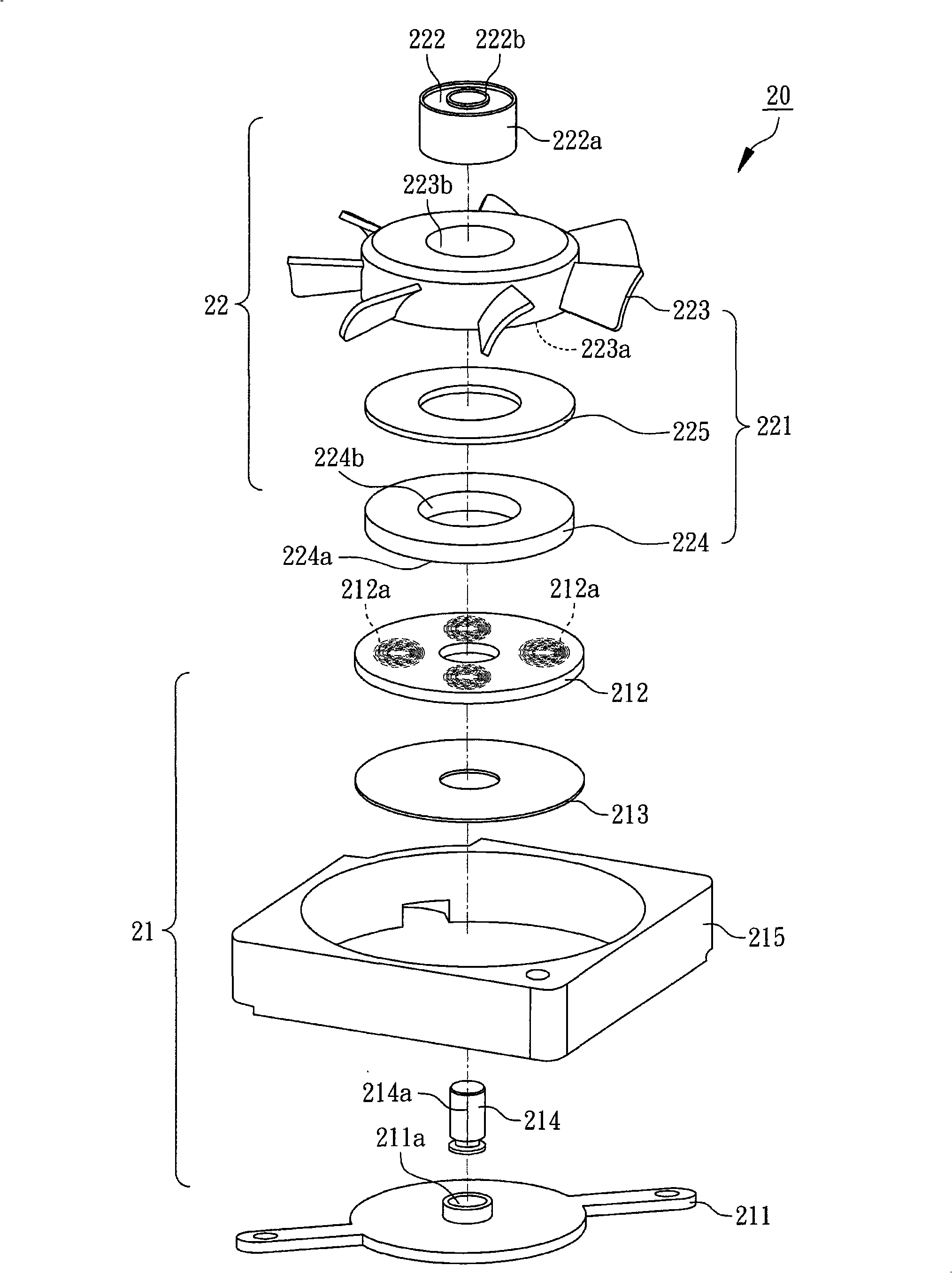
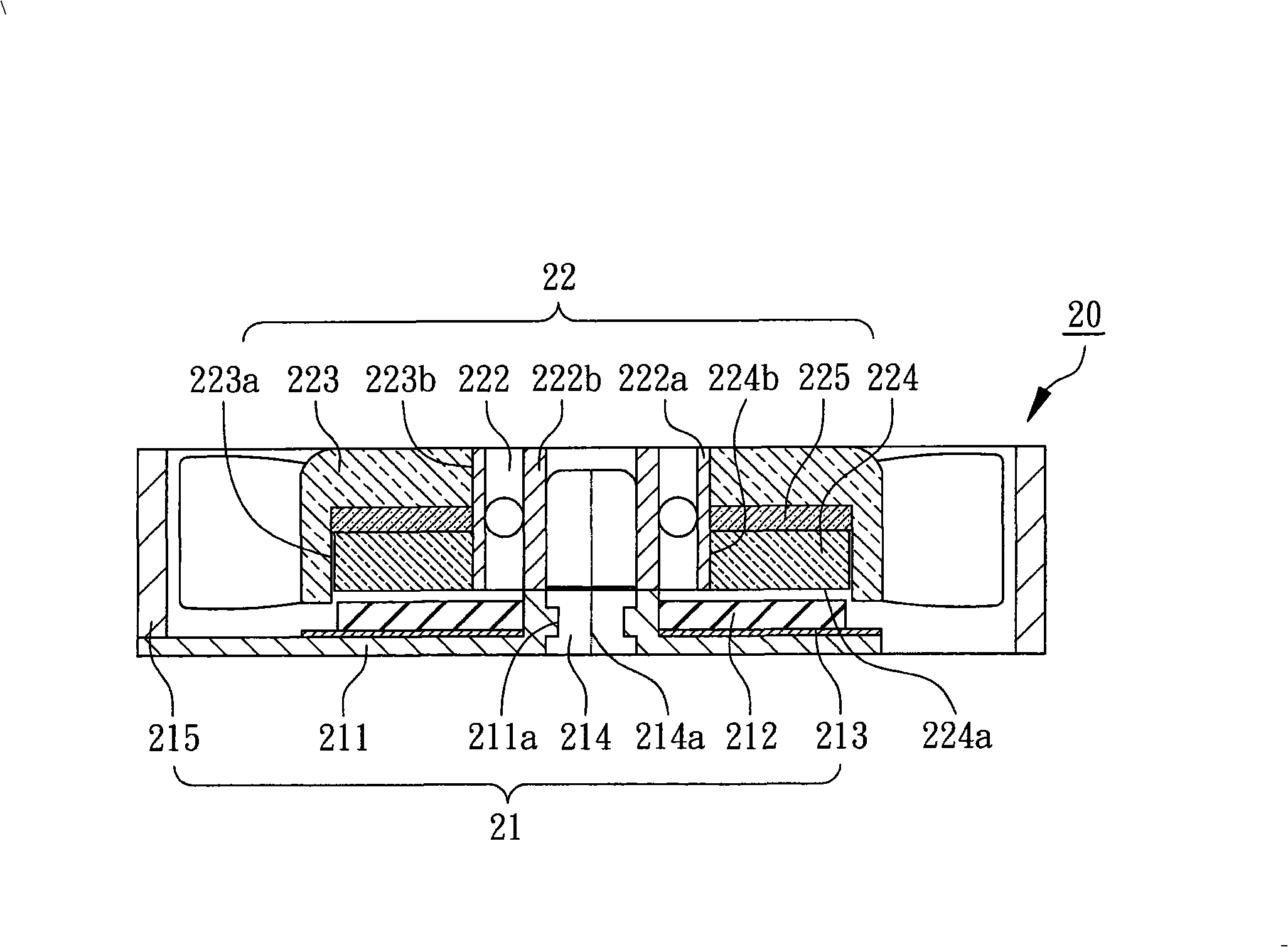
[0045] see figure 2 and 3The figure shows the first preferred embodiment of the present invention. A thin fan structure 20 includes a driving assembly 21 and a rotating assembly 22. In this embodiment, the driving assembly 21 includes a base 211 and a coil Circuit board 212, an insulating sheet 213 and an axis 214, the material of the base 211 can be metal, preferably, the material of the base 211 is ferrous metal, and the coil circuit board 212 is arranged on the base 211 , the coil circuit board 212 has an embedded coil winding 212a, the embedded coil winding 212a is used to d...


PUM


Abstract

The invention relates to a thin fan structure, which comprises a driving component and a runner assembly, wherein, the driving component includes a base, a coil circuit board and an axle center, the coil circuit board is arranged on the base; the runner assembly includes a bearing, a segment gear, a ferrous metal sheet and a magnet, the bearing is provided with an outer ring and an inner ring, the segment gear, the ferrous metal sheet and the magnet are fixed at the outer ring of the bearing, and the inner ring of the bearing is fixed at the axle center of the driving component, meanwhile, the coil circuit board of the driving component can drive the runner assembly to rotate. The thin fan structure of the invention can greatly reduce the overall construction thickness and weight of the fan structure, meet the requirements for lightness, tenuity and shortness of the fan and effectively expand the application range of the fan.

Description

technical field [0001] The invention relates to a fan structure, in particular to a thin fan structure. Background technique [0002] like figure 1 As shown, the existing conventional fan structure 10 includes a housing 11, a bearing 12, a shaft 13, a fan wheel 14, a stator 15, a silicon steel sheet 16 and a magnet 17. The housing 11 has A shaft seat 11a, the bearing 12 has an outer ring 12a and an inner ring 12b, the outer ring 12a of the bearing 12 is fixed to the shaft seat 11a of the housing 11, and the shaft rod 13 is fixed on the The inner ring 12b of the bearing 12, the fan wheel 14 is fixed on one end of the shaft 13, the stator 15 is sleeved on the shaft seat 11a of the housing 11, the silicon steel sheet 16 and the magnet 17 are fixed On an inner sidewall 14a of the fan wheel 14, when the fan structure 10 operates, the inner ring 12b of the bearing 12, the shaft 13, the fan wheel 14, the silicon steel sheet 16 and the magnet 17 rotate together, However, the exis...

Claims


Application Information

Patent Timeline
Patent Type & Authority Applications(China)
IPC IPC(8): F04D25/06F04D29/32F04D29/056F04D29/52
Inventor 陈朝景陈雪真
Owner ADDA
Why Eureka
Try Eureka