
Method for performing projection display on veins plane

A projection display and plane technology, applied in the field of projection display, can solve the problems that the correction result cannot achieve the projection display effect and the calculation error is large

Inactive Publication Date: 2010-07-28
SHANGHAI JIAOTONG UNIV
View PDF0 Cites 0 Cited by
  • Summary
  • Abstract
  • Description
  • Claims
  • Application Information

AI Technical Summary

Problems solved by technology

However, this method ignores the fact that the brightness response function of the projector and camera is a curve, which leads to large calculation errors, and the correction result cannot achieve the desired projection display effect.

Method used


Image

  • Method for performing projection display on veins plane
  • Method for performing projection display on veins plane
  • Method for performing projection display on veins plane

Examples


Embodiment Construction

[0037] The embodiments of the present invention are described in detail below in conjunction with the accompanying drawings: this embodiment is implemented on the premise of the technical solution of the present invention, and detailed implementation methods and specific operating procedures are provided, but the protection scope of the present invention is not limited to the following the described embodiment.

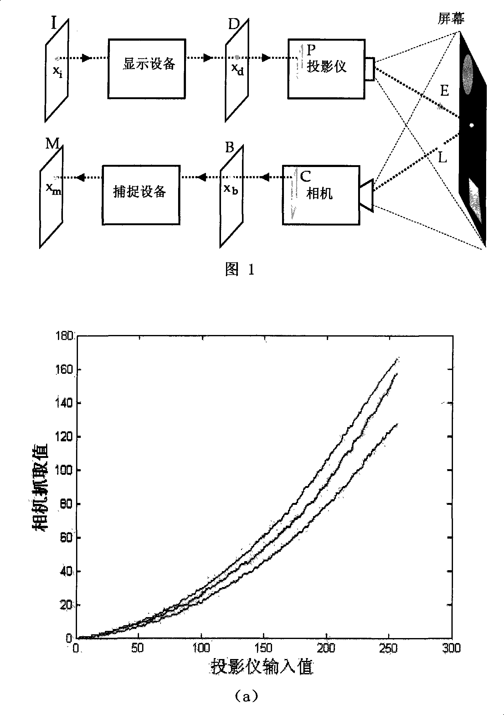
[0038] Such as figure 1 Shown, be the photometric radiation model of the projector camera system that this embodiment is used for image correction, among the figure I is the picture plane that needs to be projected and displayed, with a certain point x above i For example (x i Contains the position information and brightness information of the point, the same below), and the output result on the graphics card plane D through the display device is x d ; The output brightness of the projector P at this point is E, after x on the projection plane s Point reflection, a...


PUM


Abstract

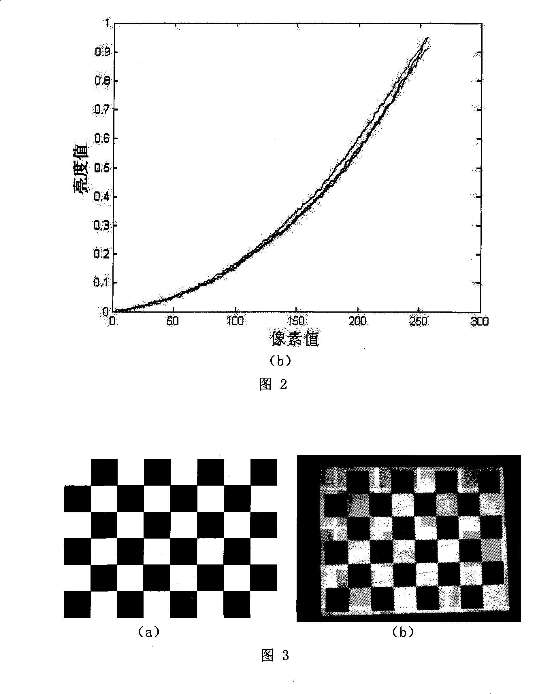
The invention provides a method for projected display on a textured plane in the technical field of computer-based image processing. In the method, firstly, a radiation model is established for showing that after the light output by a projector is reflected by a projection screen, the light is grabbed by a camera; secondly, the luminosity response function of the projector and the camera, and thecolor mixing matrices of the projector and the camera are measured; thirdly, the geometrical mapping between the projector and the plane of the camera are established through projected checkerboard images; fourthly, with the given luminosity response function of the projector and the camera, and the color mixing matrices of the projector and the camera, two gray scale images are projected, and the reflectivity information of the projected surface and the ambient light information are found; fifthly, the projected images are rectified and are projected again before the projected images are output according to the geometrical mapping as stated in the third step and the reflectivity information of the projected surface and the ambient light information as stated in the fourth step. After theprojected images are rectified and the light is accelerated through a GPU, the speed can reach 60fps and meets the requirement for real time. The method is applicable to various practical circumstances.

Description

technical field [0001] The invention relates to a projection display method in the technical field of computer image processing, in particular to a projection display method on a textured plane. Background technique [0002] As an imaging system, projection display uses various optical, electronic and mechanical components to generate various optical images between the observer and the objective world. With the development of projector hardware technology, its ever-increasing display capabilities and falling prices have made it a widely used presentation device. Since the projector can project images with larger size and higher resolution than the input image at almost any place, it is more suitable for many application fields than other ordinary desktop screen display methods, especially in augmented reality applications. . However, in actual use, the projection display method is often greatly affected by the objective environment. Images produced by projectors are often...

Claims


Application Information

Patent Timeline
Patent Type & Authority Patents(China)
IPC IPC(8): G03B21/26
Inventor 杨旭波肖双九陈新利历萌
Owner SHANGHAI JIAOTONG UNIV
Learn More