Supercharge Your Innovation With Domain-Expert AI Agents!

Motorcycle brake system

A braking system, motorcycle technology, applied to bicycle brakes, brakes, bicycle accessories, etc., can solve problems such as impact/pulsation

Inactive Publication Date: 2011-07-06
CONTINENTAL TEVES AG & CO OHG
View PDF1 Cites 0 Cited by
  • Summary
  • Abstract
  • Description
  • Claims
  • Application Information

AI Technical Summary

Problems solved by technology

[0003] A disadvantage of the described brake system is the reaction of the pump pressure on the manually actuated master brake cylinder, whereby shocks / pulsations can be felt on the hand brake lever or foot brake lever of the manually actuated master brake cylinder

Method used


Image

  • Motorcycle brake system
  • Motorcycle brake system

Examples


Embodiment Construction

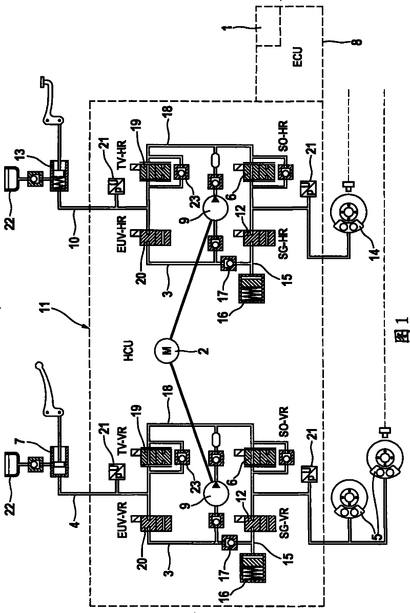
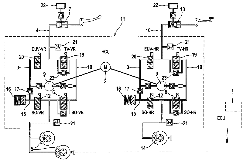
[0007] FIG. 1 shows schematically a hydraulic circuit diagram for a motorcycle brake system with the essential features of the invention. The braking system comprises hydraulically operable front and rear wheel brake circuits 4, 10 each having a master brake cylinder 7 connected to the front wheel brake circuit 4 and operable by hand and a Master brake cylinder 13 on rear wheel brake 14 actuated in proportion to foot force.

[0008] For brake slip control, solenoid-operated inlet and outlet valves 6, 12 are provided in the front and rear brake circuits 4, 10, wherein an inlet valve 6, which is open in the normal position Installed in the brake lines of the front wheel brake circuit and the rear wheel brake circuit 4, 10 respectively, these brake circuits are connected to the corresponding master brake cylinders 7, 13 through the isolation valve 19 opened in the normal position to front wheel brake 5 or rear wheel brake 14. The discharge valve 12 closed at the normal position...


PUM


Abstract

The invention relates to a dual-circuit hydraulic motorcycle brake system in which the reversing valve (20) and / or the shut-off valve (19) take / s a switching position in which the pressure generated by the pump (9) is prevented from causing a reaction in the hand-operated or foot-operated master brake cylinder (7, 13) when the pump starts working in one of the two brake circuits.

Description

technical field [0001] The invention relates to a motorcycle braking system according to the preamble of claim 1 . Background technique [0002] JP2000071963A has disclosed such a motorcycle braking system. The brake system has hydraulically actuated front and rear wheel brake circuits, which can be established together or independently of one another in the wheel brakes via foot-operated and hand-operated master brake cylinders brake pressure. For brake slip control, electromagnetically actuatable inlet and outlet valves as well as a dual-circuit pump that can be driven by an electric motor are incorporated in the brake circuits of the front and rear wheels. Furthermore, in addition to the inlet and outlet valves and the pumps, electrically operable isolating valves or directional valves are additionally provided in the two brake circuits in order to manually actuate the two main brake cylinders. For one, the brake pressure can also be built up electrohydraulically in th...

Claims


Application Information

Patent Timeline
Patent Type & Authority Patents(China)
IPC IPC(8): B60T8/32B62L3/02B60T8/42B60T8/40
CPCB60T8/4072B60T8/4291B60T8/3225B60T8/261B60T8/32B60T8/42B62L3/02B60T8/40
Inventor A·埃克特O·霍夫曼
Owner CONTINENTAL TEVES AG & CO OHG
Features
  • R&D
  • Intellectual Property
  • Life Sciences
  • Materials
  • Tech Scout
  • Unparalleled Data Quality
  • Higher Quality Content
  • 60% Fewer Hallucinations
Learn More