Glider veneer single acting rectifying stabilizer

An anti-rolling device and a technology of planing boats, which are applied in the field of ships, can solve the problems of unsuitable and unusable planing boats, and achieve the effects of compact structure, low cost and easy maintenance

Inactive Publication Date: 2008-12-24
JIANGSU UNIV OF SCI & TECH
View PDF0 Cites 11 Cited by
  • Summary
  • Abstract
  • Description
  • Claims
  • Application Information

AI Technical Summary

Problems solved by technology

Due to the particularity of the sailing state of a single planing boat and the small displacement of the hull, except for the bilge keel, the above-mentioned anti-rolling devices are basically only suitable

Method used


Image

  • Glider veneer single acting rectifying stabilizer
  • Glider veneer single acting rectifying stabilizer
  • Glider veneer single acting rectifying stabilizer

Examples


Embodiment Construction

[0020] The present invention will be further described below in conjunction with drawings and embodiments.

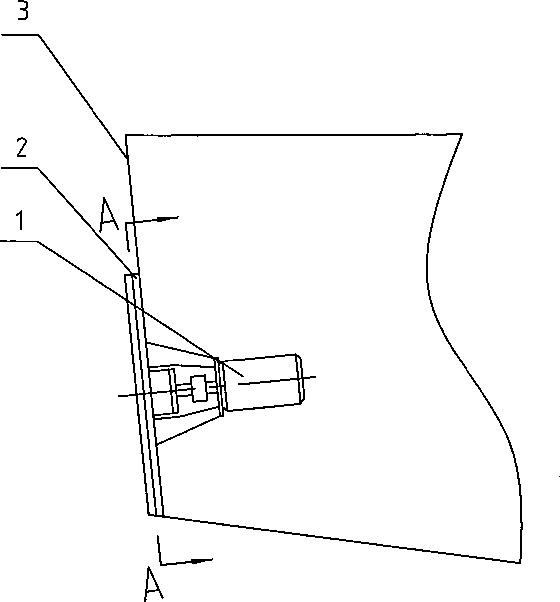
[0021] like figure 1 , image 3 and Figure 5 As shown, the present invention includes a drive mechanism 1 and an actuator 2, the drive mechanism 1 is arranged in the stern body of the planing boat, and the actuator 2 is arranged outside the stern of the planing boat. The power source of the driving mechanism 1 is a stepper motor 11, and the stepper motor 11 is fixed on the inner side of the stern cover 21 by the base 12, and the sealing device 14 is installed on the inner side of the stern cover 21, and the stepper motor The shaft 11a is connected to one end of the drive shaft 15 through an elastic coupling 13. The elastic coupling 13 in this embodiment is a drum-shaped tooth coupling, and other types of elastic couplings can also be used. The other end of the drive shaft 15 passes through the sealing device 14 and the stern seal plate 21, and the two ends of the dr...


PUM


Abstract

The invention discloses a single-plate single-action rectifying-stabilizing device for planing boats. A stepping motor shaft is connected with a drive shaft; an eccentric wheel is arranged in an oil-bearing drive slider and is fixed with the drive shaft; the oil-bearing drive slider is arranged in a rectangular hole of a top corner of a rectifying plate; a base plate is fixed outside a stern sealing plate; the rectifying plate is arranged between the base plate and a cover plate; a mandrel is supported below the rectifying plate; a plurality of anti-warp pins pass through an arc-shaped groove of the rectifying plate; and a plurality of oil-bearing sliders are respectively fixed on two sides of the rectifying plate, and a plurality of pairs of flat slide rails are correspondingly arranged on the base plate and the cover plate. The device drives the rectifying plate to rotate around the center of the mandrel arranged below the rectifying plate through the eccentric wheel and the oil-bearing drive slider, which ensures that the lower edge of the rectifying plate rotates out from the bottom edge of a planing boat and cuts into water, so as to change the water flow field under the planing boat as well as the hydrodynamic pressure center and then to reduce swing. The device only adds few components to a stern of the planing boat, which solves the problem that a boat body produces great swing when the planing boat slides and sails on water surface.

Description

technical field [0001] The invention relates to an anti-rolling device for a planing boat, in particular to an anti-rolling device for a planing boat with an adjustable flow plate. The present invention is applicable to the planing boat of flat stern sealing plate. It belongs to the field of ship technology. Background technique [0002] When a planing boat sails at high speed on the water surface, due to the action of wind, waves, and currents, the hull will sway considerably, which poses a threat to the safety of the crew, equipment and boat, especially for military boats, which will make weapons unable to Normal launch, so as to delay the fighter. There are many types of traditional ship anti-rolling devices, mainly the following: bilge keels, anti-rolling water tanks, and anti-rolling fins. Due to the particularity of the sailing state of a single planing boat and the small displacement of the hull, except for the bilge keel, the above-mentioned anti-rolling devices a...

Claims


Application Information

Patent Timeline
IPC IPC(8): B63B39/06
Inventor 周玉龙杨松林
Owner JIANGSU UNIV OF SCI & TECH
Why Eureka
Try Eureka