Supercharge Your Innovation With Domain-Expert AI Agents!

Display device

A technology for display devices and screens, applied in projection devices, optics, instruments, etc., can solve problems such as loading large loads, lack of stability, and heavy weight

Inactive Publication Date: 2008-12-24
SEIKO EPSON CORP
View PDF0 Cites 9 Cited by
  • Summary
  • Abstract
  • Description
  • Claims
  • Application Information

AI Technical Summary

Problems solved by technology

[0005] However, since the projection unit is equipped with a plurality of lenses for magnifying and projecting the image light, the weight becomes heavy. Therefore, in the integrated reflective projection system described in Patent Document 1, when the screen is installed approximately vertically, the weight is balanced. Poor, may lack stability
Moreover, a large load is applied to the part connecting the screen and the arm and the arm itself.
Therefore, there is a problem that the system needs to be reinforced, and the system becomes larger and heavier.

Method used


Image

  • Display device
  • Display device
  • Display device

Examples


no. 1 Embodiment approach

[0044] Hereinafter, the display device in the first embodiment will be described with reference to the drawings.

[0045] The display device of this embodiment is a device that projects image light from a projection unit to a screen to display an image.

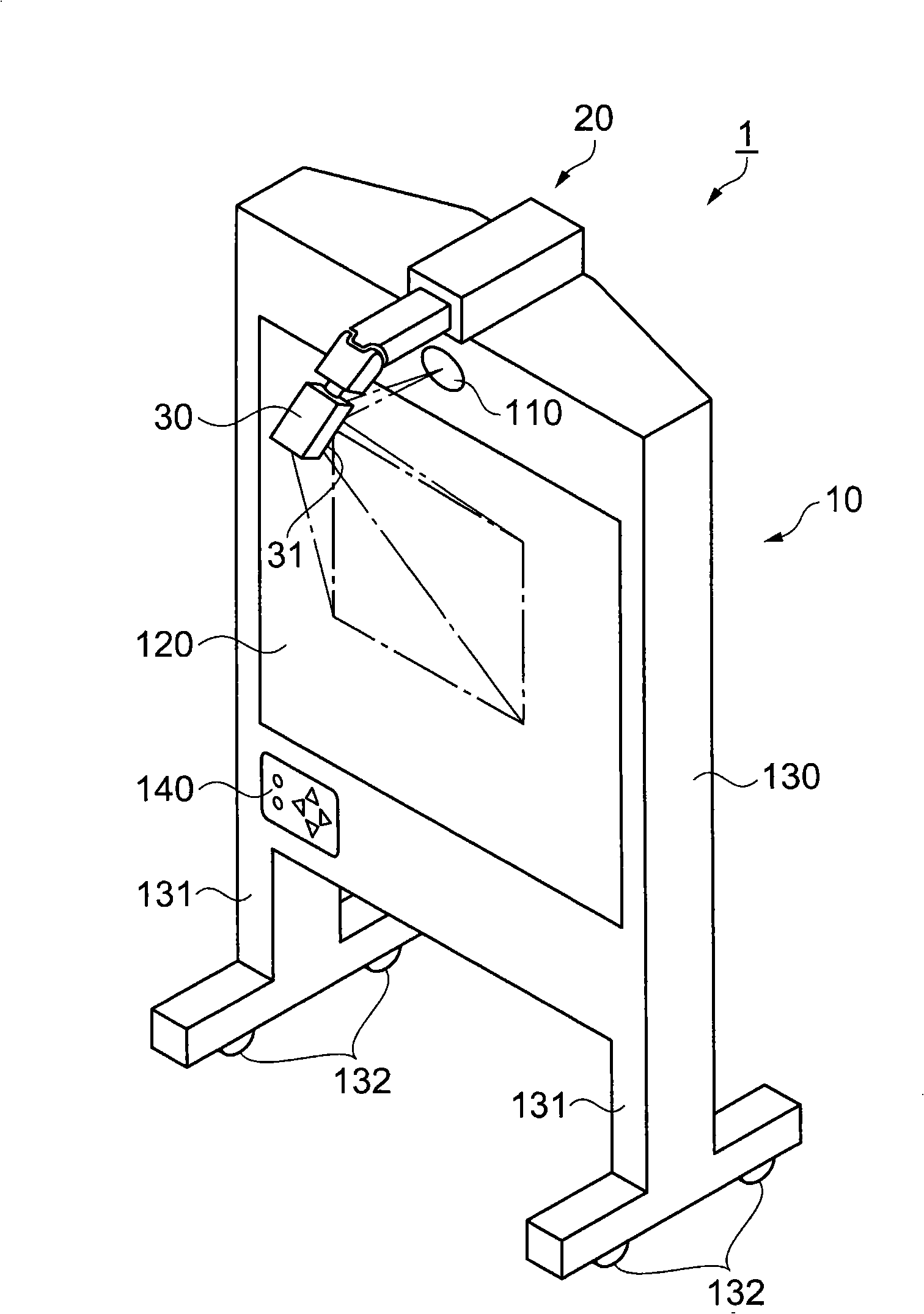
[0046] figure 1 It is a figure which shows the external appearance of the display device of this embodiment, and is a perspective view seen from the upper side.

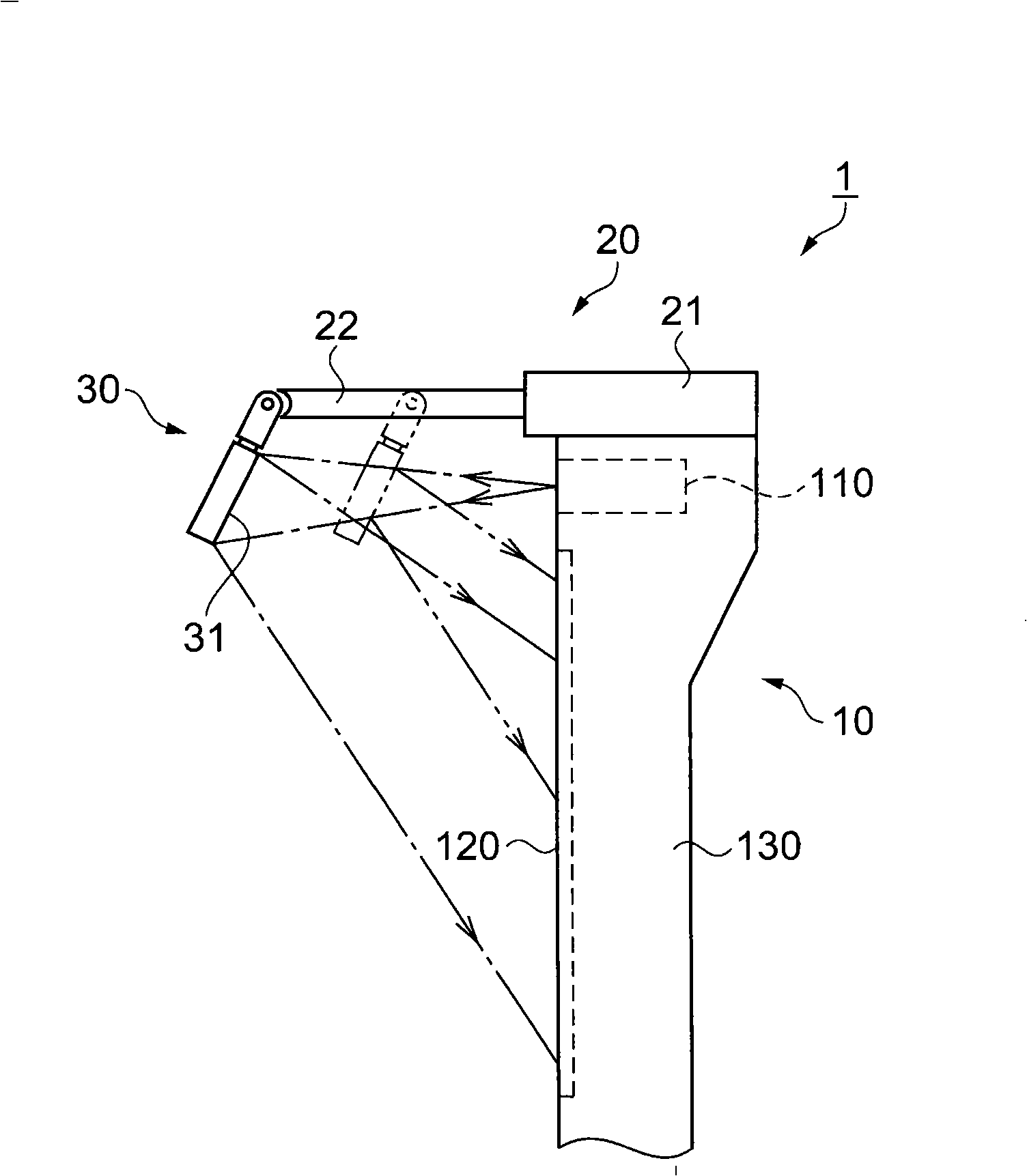
[0047] As shown in figure 1 Ground, the display device 1 has: a screen unit 10, an arm portion 20, and a reflection unit 30. The screen unit 10 includes a screen 120 that is viewed as a quadrangular shape and is held by a housing 130, and a projection unit 110 that is housed in a substantially central portion of the upper portion of the housing 130. Furthermore, above the projection unit 110, the arm portion 20 is installed protruding from the screen unit 10, and at the tip of the arm portion 20, a reflection unit 30 having a mirror 31 is installed. In addition, the p...

no. 2 Embodiment approach

[0098] Next, the display device 1 in the second embodiment will be described with reference to the drawings.

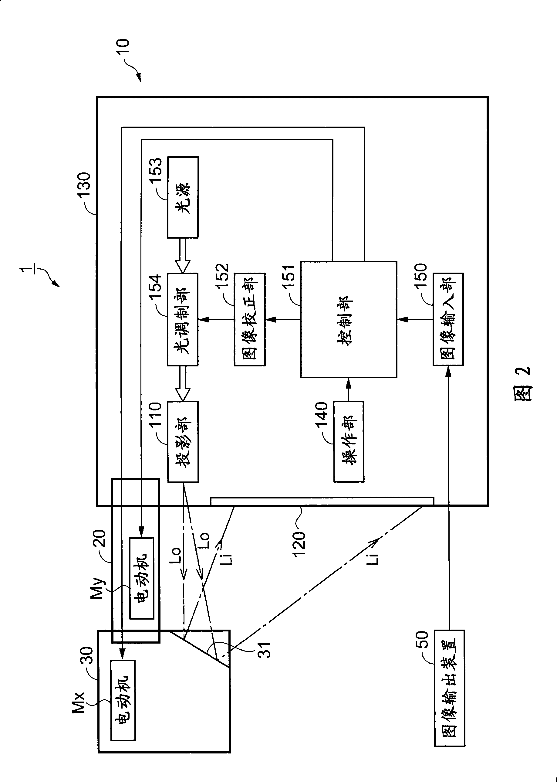
[0099] FIG. 9 is a block diagram illustrating the schematic configuration of the display device 1 of this embodiment. Picture 10 It is a diagram showing its appearance.

[0100] As shown in Figure 9, Picture 10 Specifically, the display device 1 of this embodiment is configured by adding a reading unit 155, a printing unit 156, and an interface unit 157 to the screen unit 10 of the first embodiment. In addition, the screen 120 is composed of a white board. In addition, the operation unit 140 is provided with a read key (not shown) for operating the reading unit 155 and a print key (not shown) for operating the printing unit 156.

[0101] Since the screen 120 is composed of a whiteboard, it can display images generated by projection from the projection unit 110, and can write characters, drawings, etc. by handwriting using a marker pen or the like, and erase them with an...

no. 3 Embodiment approach

[0111] Next, the display device 1 in the third embodiment will be described with reference to the drawings.

[0112] FIG. 11 is a block diagram explaining the schematic configuration of the display device 1 of this embodiment.

[0113] As shown in FIG. 11, the display device 1 of this embodiment is configured to include an imaging unit 158 ​​on the arm 20 instead of the reading unit 155 of the screen unit 10 of the second embodiment. In addition, the operation unit 140 is provided with an imaging key (not shown) for operating the imaging unit 158 ​​instead of the read key.

[0114] When the imaging key or the printing key is operated, the imaging unit 158 ​​captures the entire surface of the screen 120 according to an instruction from the control unit 151, and outputs the captured image to the control unit 151 as an image signal.

[0115] The control unit 151 stores the image signal output from the imaging unit 158 ​​when the imaging key is operated; when the printing key is opera...


PUM


Abstract

The present invention provides display device with high setting stability quality. A screen (120) is held on a frame body (130), a projection portion (10) is arranged at the central part of the frame body (130), an arm portion (20) is installed above the projection portion (10) with a projecting screen (120) mode, a reflecting unit (30) with a reflecting error (31) is installed at the front of the arm portion (20), a projection portion projects to an image light from an opening portion which is faced to the reflecting unit (30) and arranged at the front side of the frame body (130), and the reflecting unit (30) reflects the image light to the screen (120) and displays the image on the screen (120). The reflecting unit (30) can change the reflecting direction of the image light, therefore it can change the position of the image displayed on the screen (20) at up-and-down and left-right directions.

Description

Technical field [0001] The present invention relates to a display device that projects image light on a screen to display an image. Background technique [0002] In meeting rooms, classrooms, etc., a projector that projects image light on a screen is used. When using this projector, it is necessary to provide space for both the screen and the projector. Generally, the screen is installed approximately vertically, and the projector is installed at a position separate from the screen. Therefore, if the presenter enters between the projector and the screen, the image light projected from the projector will be blocked. In addition, when a viewer views an image from behind the projector, the projector itself enters the viewer's line of sight, and there are cases where the entire image projected on the screen cannot be viewed. [0003] Therefore, an integrated reflective projection system that can be installed in a narrow space and that the projector and the screen are integrally forme...

Claims


Application Information

Patent Timeline
Patent Type & Authority Applications(China)
IPC IPC(8): G03B21/28G03B21/00
CPCG03B21/28G03B21/53
Inventor 翠川博
Owner SEIKO EPSON CORP
Features
  • R&D
  • Intellectual Property
  • Life Sciences
  • Materials
  • Tech Scout
  • Unparalleled Data Quality
  • Higher Quality Content
  • 60% Fewer Hallucinations
Learn More