Method for preparation of lithographic printing plate

a technology lithographic printing plate, which is applied in the field of preparation of lithographic printing plate, can solve the problems of poor development property and unevenness

Active Publication Date: 2008-07-03
FUJIFILM CORP
View PDF6 Cites 13 Cited by
  • Summary
  • Abstract
  • Description
  • Claims
  • Application Information

AI Technical Summary

Benefits of technology

[0019]According to the present invention, a method for preparation of a lithographic printing plate which provides a good printed material havi

Problems solved by technology

However, hitherto known methods for preparation of a lithographic printing plate including development with an aqueous near-neutral solution have problems in that the developing property is poor, i

Method used


Image

  • Method for preparation of lithographic printing plate
  • Method for preparation of lithographic printing plate
  • Method for preparation of lithographic printing plate

Examples


examples

[0449]The present invention will be described in more detail with reference to the following examples, but the invention should not be construed as being limited thereto.

(Components Used)

[0450](A) A solution containing 32.4% by weight of a methyl methacrylate / methacrylic acid-copolymer (weight ratio of methyl methacrylate / methacrylic acid=4:1; acid value=110 mg KOH / g) in 2-butanone (viscosity=105 mm2 / s at 25° C.)

(B) A solution containing 88.2% by weight of a reaction product of 1 mole of 2,2,4-trimethylhexamethylene diisocyanate and 2 moles of hydroxyethyl methacrylate (viscosity=3.30 mm2 / s at 25° C.)

(C) Mono Z1620, a solution containing 30.1% by weight of a reaction product of 1 mole of hexamethylene diisocyanate, 1 mole of 2-hydroxyethyl methacrylate and 0.5 moles of 2-(2-hydroxyethyl)piperidine in 2-butanone (viscosity=1.7 mm2 / s at 25° C.)

(D) 1,4-Distyryl-(3,5-trimethoxy-4-(2-butyl)oxy)benzene

(E) Heliogene blue D7490® dispersion (9.9% by weight, viscosity=7.0 mm2 / s at 25° C.), tr...

example 4

[0486]Lithographic printing plate precursor (1) was subjected to image exposure by a violet semiconductor laser plate setter Vx9600 wherein the InGaN semiconductor laser (emission: 405 nm±10 mm / output: 30 mW) was replaced with a semiconductor laser having output of 100 mW. As for the image, halftone dots of 50% were drawn using an FM screen (TAFFETA 20, produced by Fuji Film Co., Ltd.) in a plate surface exposure amount of 0.25 mJ / cm2 and at resolution of 2,438 dpi.

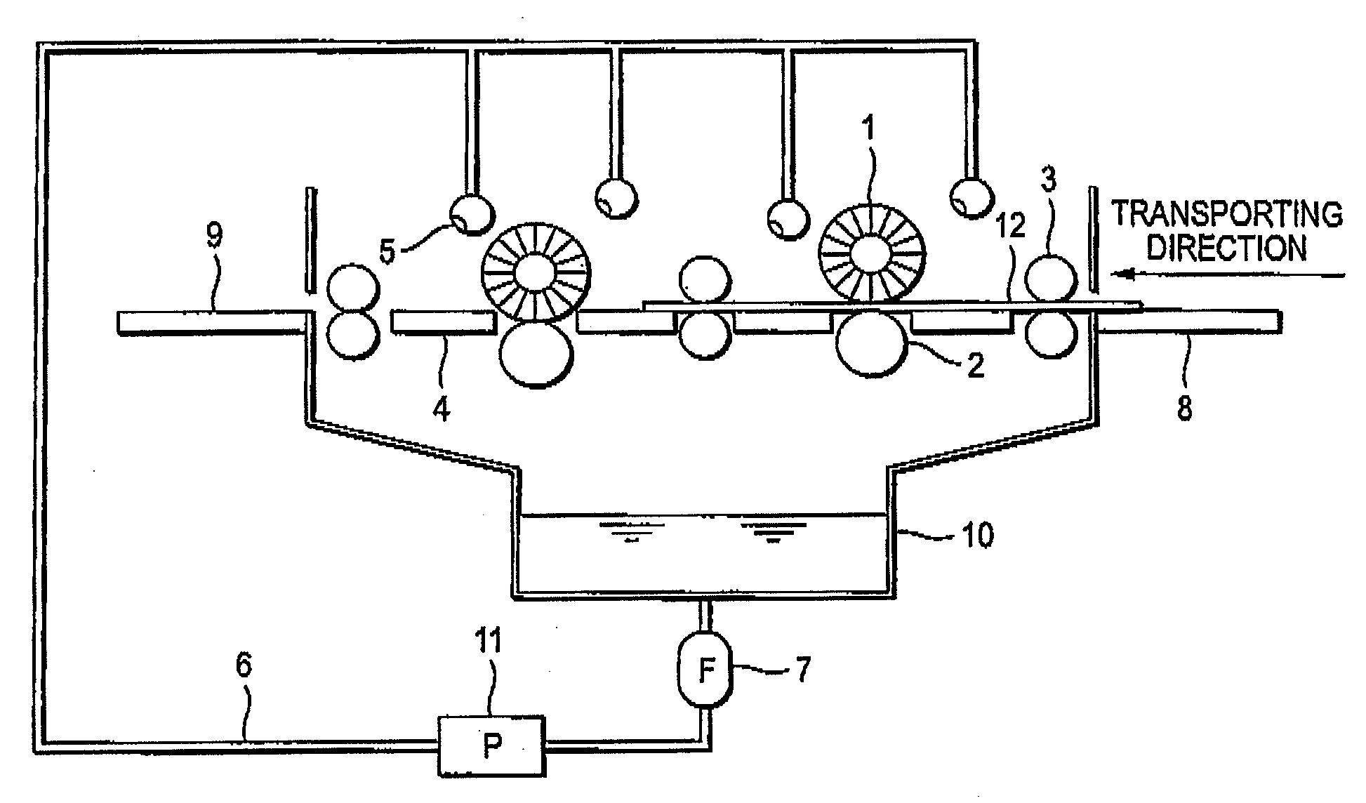
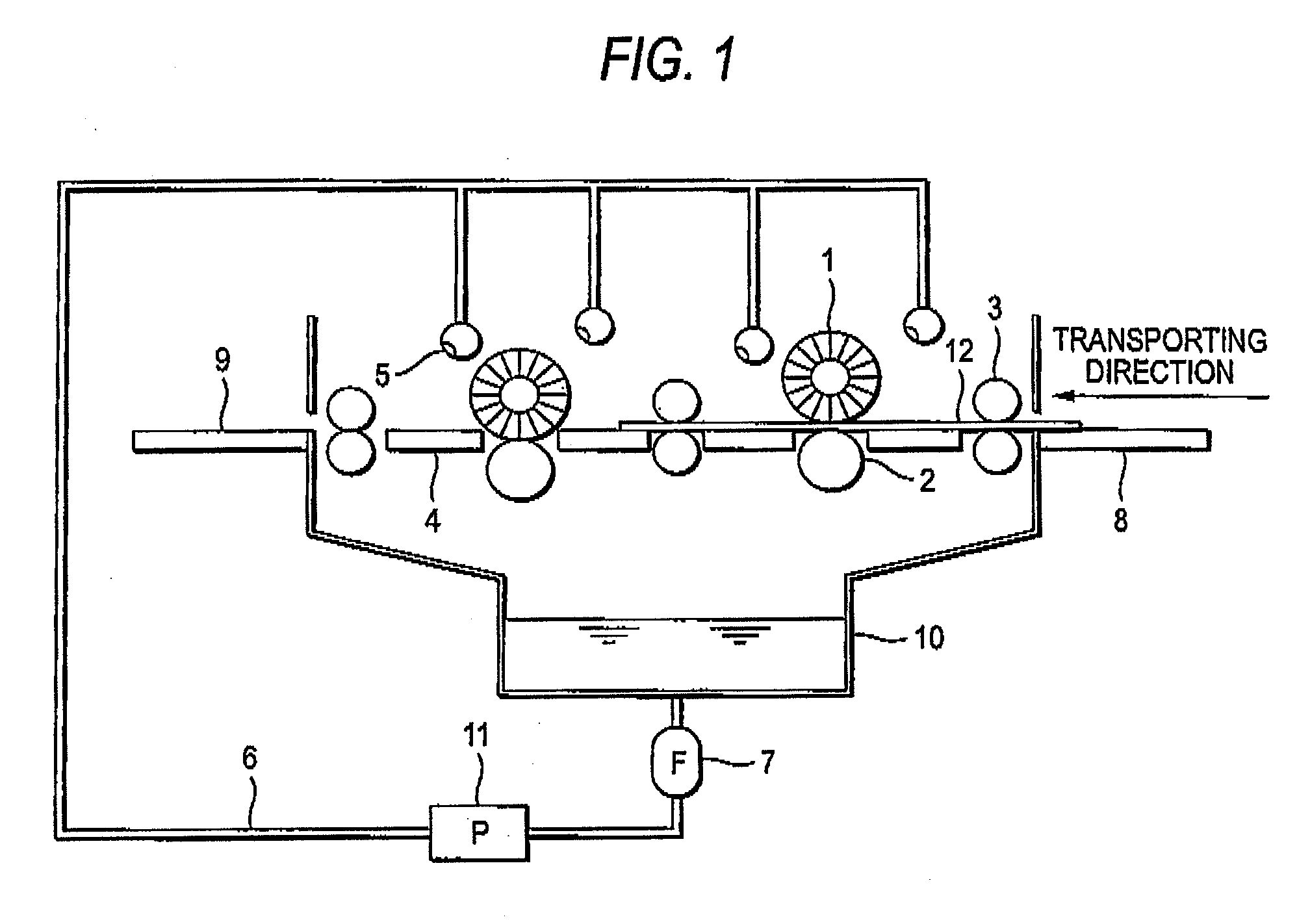
[0487]The exposed lithographic printing plate precursor was without performing the preheat, subjected to the development processing in the automatic development processor having a structure shown in FIG. 1 using Developer (1). The developing property and printing image-forming property were evaluated in the same manner as in Example 1 and the good results of the evaluation same as in Example 1 were obtained.

examples 9 to 22

[0489]The evaluation of developing property and printing image-forming property was conducted in the same manner as in Example 1 using each of Lithographic printing plate precursors (2) to (15). The results of the evaluation are shown in Table 14.

TABLE 14PrintingImage-formingPropertyUneven-Lithographicness ofPrintingHalftonePlateDevelopingDotPrecursorDeveloperPropertyStainImageExample 9(2)(1)◯◯◯Example 10(3)(1)◯◯◯Example 11(4)(1)◯◯ΔExample 12(5)(1)◯◯◯Example 13(6)(1)◯◯◯Example 14(7)(1)◯◯◯Example 15(8)(1)◯◯◯Example 16(9)(1)◯◯ΔExample 17(10)(1)◯◯◯Example 18(11)(1)◯◯◯Example 19(12)(1)◯◯◯Example 20(13)(1)◯◯ΔExample 21(14)(1)◯◯ΔExample 22(15)(1)◯◯Δ


PUM


Abstract

A method for preparation of a lithographic printing plate including: exposing with a laser a lithographic printing plate precursor including a support and a photosensitive layer containing a sensitizing dye, a radical polymerization initiator, a radical polymerizable compound and a binder polymer; and subjecting the exposed lithographic printing plate precursor to development processing with a developer having pH of from 3 to 9 to remove an unexposed area of the photosensitive layer, wherein the binder polymer is a polymer having an acid value of from 10 to 250 mg-KOH/g and the developer contains a compound represented by one of the formulae <1>, <2> and <3> defined herein.

Description

FIELD OF THE INVENTION[0001]The present invention relates to a method for preparation of a lithographic printing plate.BACKGROUND OF THE INVENTION[0002]In general, a lithographic printing plate has a surface composed of an oleophilic image area and a hydrophilic non-image area. Lithographic printing is a printing method comprising supplying alternately dampening water and oily ink on the surface of lithographic printing plate, making the hydrophilic non-image area a dampening water-receptive area (ink unreceptive area) and depositing the oily ink only to the oleophilic image area by utilizing the nature of the dampening water and oily ink to repel with each other, and then transferring the ink to a printing material, for example, paper.[0003]In order to produce the lithographic printing plate, a lithographic printing plate precursor (PS plate) comprising a hydrophilic support having provided thereon an oleophilic photosensitive layer (image-recording layer) has heretofore been broad...

Claims


Application Information

Patent Timeline
IPC IPC(8): G03F7/038
CPCG03F7/002G03F7/322G03F7/031
Inventor INNO, TOSHIFUMIADACHI, KEIICHI
Owner FUJIFILM CORP
Why Eureka
Try Eureka