

Drinking tool
A technology for drinking mouths and containers, which is applied in the directions of closing, packaging, sealing parts with discharge devices, etc., can solve problems such as reducing the weight of container necks
- Summary
- Abstract
- Description
- Claims
- Application Information
AI Technical Summary
Problems solved by technology
Method used
Image

Examples
no. 2 example
[0054] A second embodiment of the closure is shown in Figures 5 and 6 (where the same reference numerals are used for the same parts). The design is the same as the first embodiment, except for the connection part 50 at the base of the nozzle 6, the base of the housing 4 and the method of assembly.
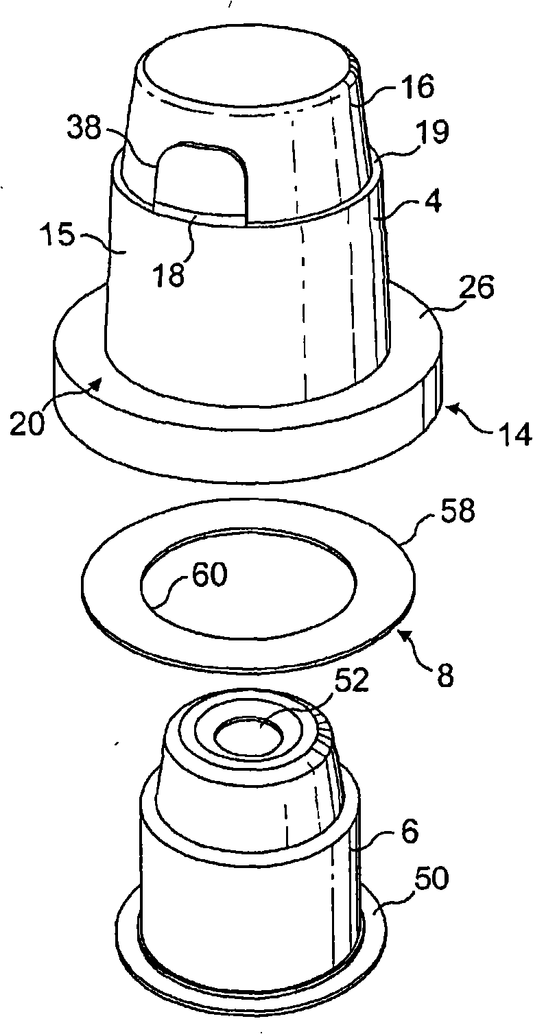
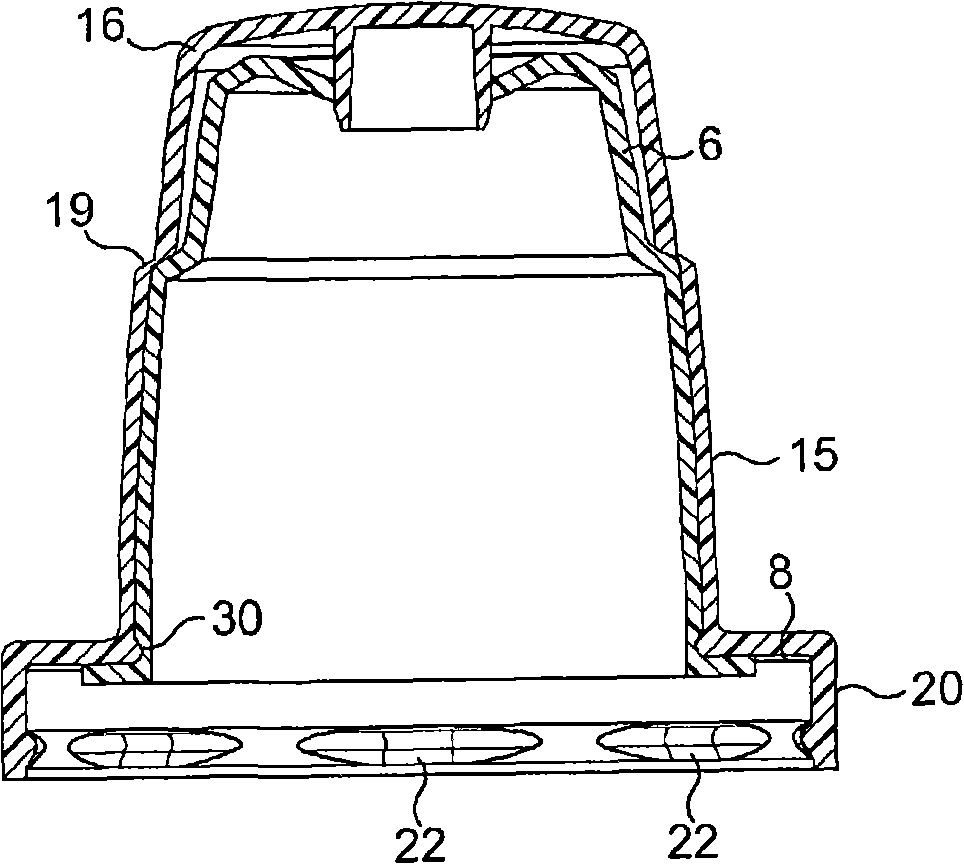
[0055] In this embodiment, the overcap 16 is connected to the base 14 by a tamper evident strap 18 . The base 14 has a skirt 20 terminating in a lip 22 adapted to snap fit an outwardly protruding bead 24 at the edge of the container neck 10 .
[0056] The skirt 20 depends from an annular bottom plate 26 which covers the exterior of the opening of the neck 10 . In this embodiment, the bottom plate 26 is stepped to define an internal recess 28 . Although an annular base plate of uniform width is shown in Figure 5, it will be appreciated that the circular opening 30 in the base plate housing the nozzle 6 may be offset to one side for easier access by consumers.
[0057] A shaped h...
no. 3 example
[0066] In Figure 7 (where the same reference numerals are used for the same parts) a third embodiment of the closure is shown. The design is similar to the first embodiment, except that the nozzle 6 is not centered within the base 14 but is offset, and a new sealing shutter arrangement is also shown on the connection part 50 . Also, an alternative nozzle profile is shown, with the top cap having a second outer valve seal 82 concentric with the valve seal 42 so as to engage the outer surface of the nozzle 6 . This embodiment is assembled in the same manner as the first embodiment.
[0067]The connection part 50 terminates in a depending shutter wall 80 designed to be push-fit within the open neck 10 of the container 12 . This is particularly advantageous when the closure is used on containers containing pressurized substances such as carbonated beverages. In this situation, pressure will act to press the shutter wall 80 against the neck, thereby holding the closure in place. ...
no. 4 example
[0070] Figure 8 The closure shown differs from the first embodiment only in that it is designed to fit in a conventional manner on a standard preform of any commonly used size (eg 28mm, 30mm, 33mm, 35mm, 38mm and 43mm or 45mm). On the PCO neck (neck finish). The skirt 20 has internal threads 70 that mate with external threads on standard necks. The lower edge of the skirt 20 may be connected to the tamper evident strip 72 by a breakable bridge 74 . This embodiment of the closure can be employed without requiring any modification to existing bottles.
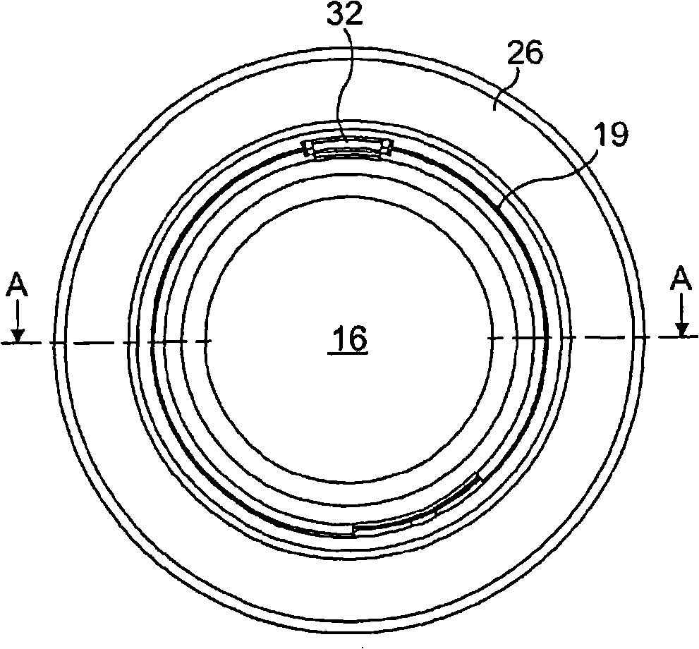
[0071] transform
[0072] Although a separate hinge 32 has been described, the hinge could be formed by leaving a portion of the tamper evident strap 18 as a permanent connection between the overcap and the base.
[0073] The tamper evident element 18 can also be omitted and the lower edge of the top cap 16 can be attached to the base by a frangible area. The visor 40 must then be strong enough so that the user can use it...
PUM
 Abstract
Description
Claims
Application Information