Tubular pile die screw

A mold and screw technology, applied in the field of molding equipment, can solve the problems of low production efficiency, large and heavy pipe pile mold screws, etc., and achieve the effect of convenient mold clamping and high production efficiency

Active Publication Date: 2010-06-30
GUANGDONG SANHE PILE CO LTD
View PDF0 Cites 20 Cited by
  • Summary
  • Abstract
  • Description
  • Claims
  • Application Information

AI Technical Summary

Problems solved by technology

[0002] The existing cement prefabricated pipe piles for construction need to use a pipe pile mold screw when forming. The existing pipe pile mold screws, the mold clamping screws are hung on the lower mold, and the screws must be turned over when clamping the mold. Come up, align and then tighten, and when turning up, because the pipe pile mold screws are relatively large and heavy, it is difficult to turn up and align, the mold is difficult to close, time-consuming and laborious, and the production efficiency is low.

Method used


Image

  • Tubular pile die screw
  • Tubular pile die screw
  • Tubular pile die screw

Examples


Embodiment Construction

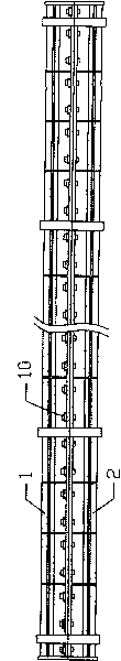
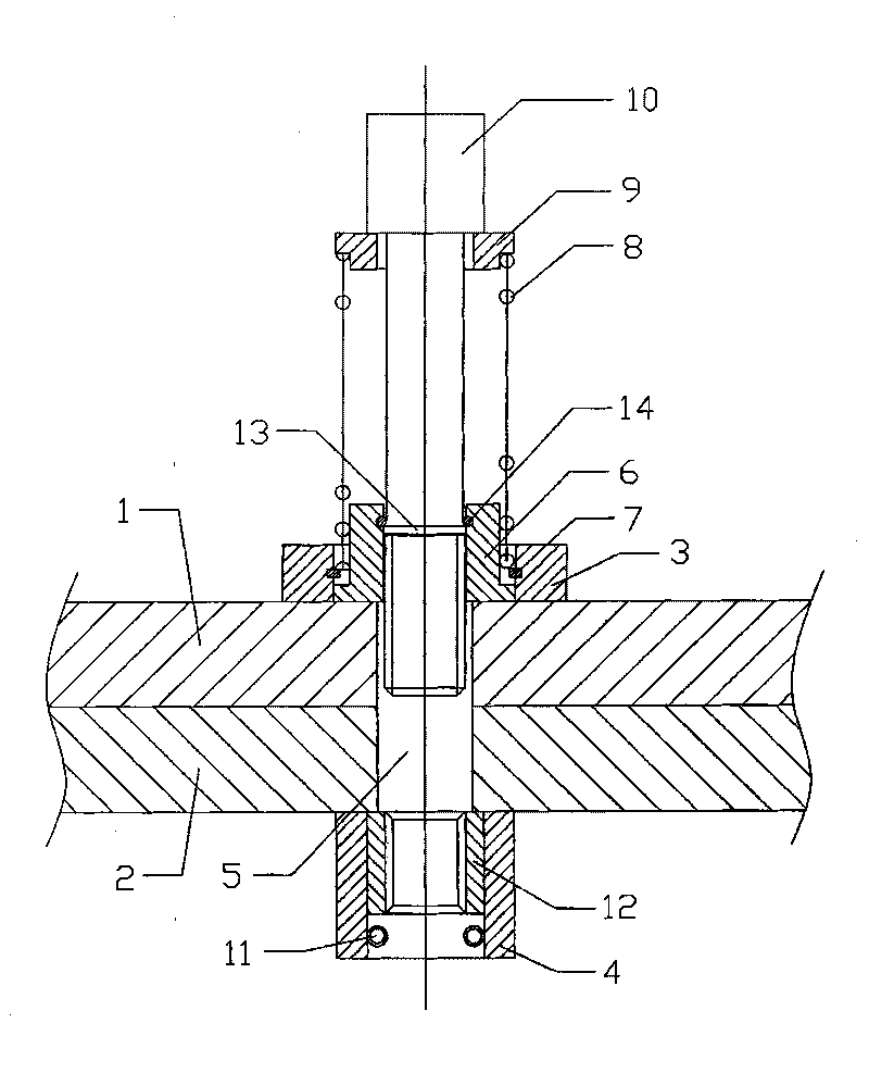
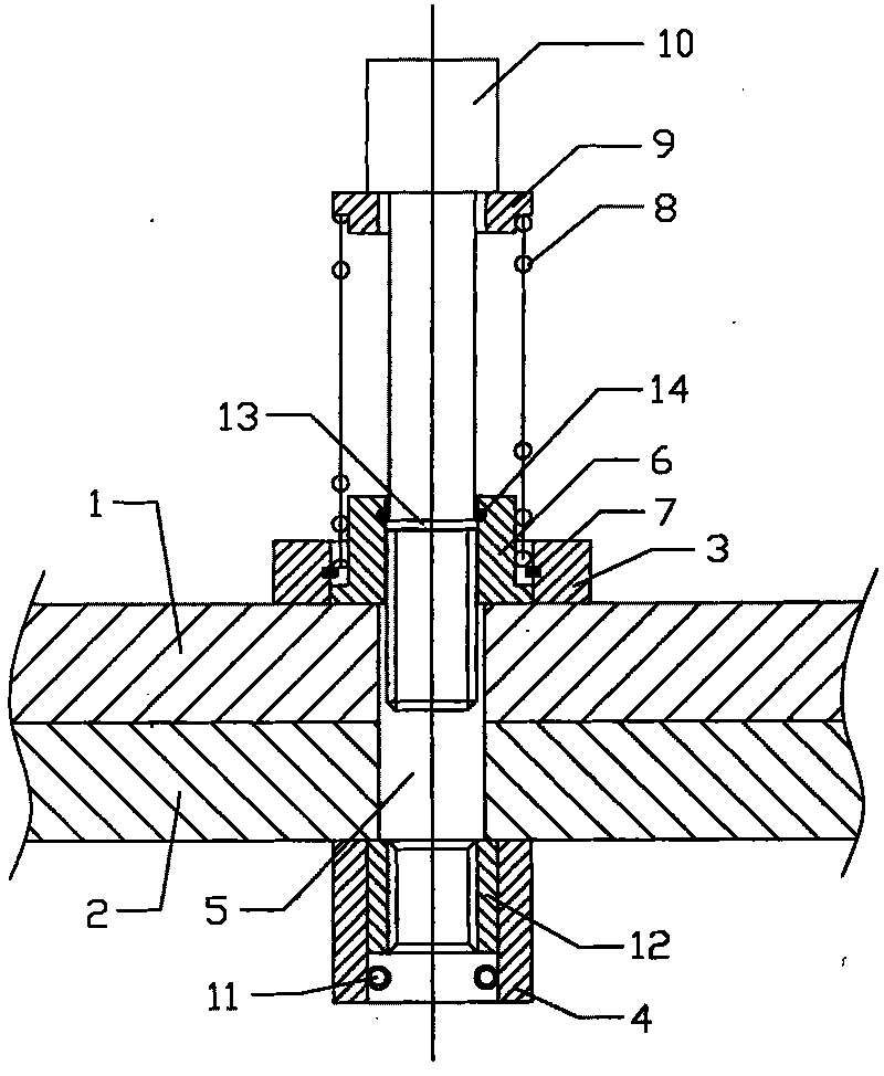
[0010] refer to figure 1 , figure 2 , a pipe pile mold screw of the present invention, comprising an upper mold 1 and a lower mold 2, the edges of the upper mold 1 and the lower mold 2 are correspondingly fixed with a plurality of upper seats 3 and lower seats 4, and the bolt fixing holes 5 penetrate the upper seat 3 , upper die 1, lower die 2 and lower seat 4, the upper seat 3 is provided with a spring pad 6, the lower spring pad 6 is clamped in the upper seat 3 by a snap ring 7, between the lower spring pad 6 and the upper seat 3 A spring 8 is sleeved, and the upper end of the spring 8 is covered with an upper spring pad 9, and a bolt 10 runs through the upper spring pad 9, spring 8, lower spring pad 6, bolt fixing holes 5 and the lower seat 4 from top to bottom. 4 is provided with a nut 12 for locking the bolt 10 through a latch 11, the bottom of the bolt 10 is fixed with a protruding ring 13, and the inner side of the lower spring pad 6 is fixed with a protruding ring 13...


PUM


Abstract

The invention discloses a tubular pile die screw, which comprises an upper die and a lower die, wherein the edges of the upper die and the lower die are correspondingly fixedly provided with a plurality of upper seats and lower seats, bolt fixing holes run through the upper seats, the upper die, the lower die and the lower seats, a lower spring pad is arranged in the upper seat, the lower spring pad is clamped in the upper seat via a clamp spring, a spring is sleeved between the lower spring pad and the upper seat, the upper end of the spring is sleeved with an upper spring pad, a bolt penetrates through the upper spring pad, the spring, the lower spring pad, the bolt fixing hole and the lower seat from top to bottom, a nut used for locking the bolt is clamped in the lower seat via an inserted pin, the lower part of the bolt is fixedly provided with a convex ring, the inner side of the lower spring pad is fixedly provided with an inner clamping ring used for clamping the convex ring and preventing the bolt from dropping, and after the nut is unscrewed, the spring jacks up the bolt and makes the bolt separated from the lower die. The die clamping screw arranged on the upper die can not loose, the die clamping is convenient, the die can be clamped well by directly screwing the bolt, and the production efficiency is high.

Description

technical field [0001] The invention relates to a molding device for building materials, in particular to a pipe pile mold screw. Background technique [0002] The existing cement prefabricated pipe piles for construction need to use a pipe pile mold screw when forming. The existing pipe pile mold screws, the mold clamping screws are hung on the lower mold, and the screws must be turned over when clamping the mold. Come up, align and then tighten, and when turning up, because the pipe pile mold screws are relatively large and heavy, it is difficult to turn up and align, the mold is difficult to close, time-consuming and laborious, and the production efficiency is low. Therefore, it is necessary to make improvements. Contents of the invention [0003] In order to solve the above problems, the object of the present invention is to provide a mold screw for pipe piles, which can not be loosened when the mold clamping screw is installed on the upper mold, is convenient for mol...

Claims


Application Information

Patent Timeline
Patent Type & Authority Applications(China)
IPC IPC(8): B28B21/76
Inventor 韦泽林
Owner GUANGDONG SANHE PILE CO LTD
Why Eureka
Try Eureka