Assembling method of mold-cavity liner

A technology of mold core insertion and assembly method, applied in the field of mold assembly, can solve the problems of air dust pollution, deterioration of optical lens quality, low stability of mold core body 12, etc., and achieves the effects of less wear and avoidance of mold eccentricity

Inactive Publication Date: 2011-03-30
HONG FU JIN PRECISION IND (SHENZHEN) CO LTD +1
View PDF0 Cites 0 Cited by
  • Summary
  • Abstract
  • Description
  • Claims
  • Application Information

AI Technical Summary

Problems solved by technology

However, since the mold core base 12 is perpendicular to the workbench 16, the stability of the mold core base 12 itself is not high, so it cannot be guaranteed that it has a higher Stability, so it is difficult to ensure the concentricity of the mold
In addition, the molding surface of the mold insert 14 is exposed to a large extent during the assembly process, and is easily polluted by air dust, which will also cause a decline in the quality of the molded optical lens

Method used


Image

  • Assembling method of mold-cavity liner
  • Assembling method of mold-cavity liner
  • Assembling method of mold-cavity liner

Examples


Embodiment Construction

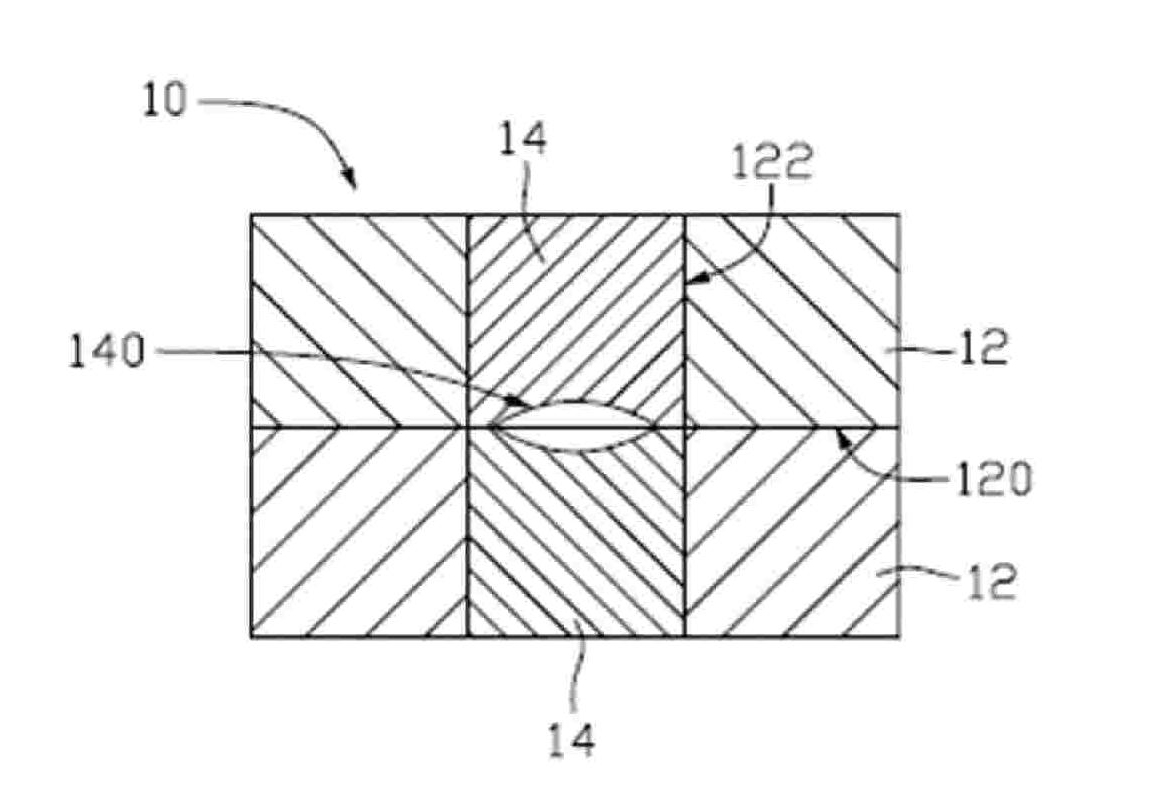
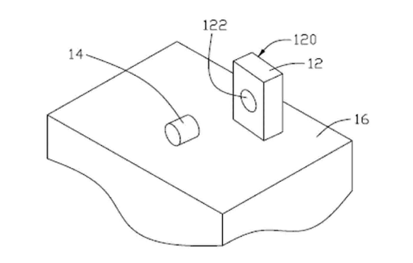
[0016] The first embodiment of the present invention provides a method for assembling a mold core insert, which mainly includes the following steps: 1). Provide a mold core base body and a mold core insert with a molding surface, the mold core base body has A clamping surface with several screw holes formed on the clamping surface, and the base of the mold core also has a cavity for inserting the core through the base of the mold core; 2). Drill the screw into the screw hole of the base of the mold core ; 3). Place the base of the mold core horizontally on the workbench, with the clamping surface of the base of the mold core facing the workbench, and adjust the height of the screw so that the base of the mold core is placed horizontally on the workbench; 4). Put the core of the mold into the Assemble the mold core into the sub-cavity with the molding surface facing the workbench; 5). Take out the screws.

[0017] The method in this embodiment will be described in detail below ...


PUM

PropertyMeasurementUnit
diameteraaaaaaaaaa

Abstract

The invention relates to a die cavity core assembly method, comprising the steps as follows: a die cavity substrate and a die cavity core with forming surfaces are provided, wherein the die cavity substrate is provided with a die closing surface, the die cavity substrate is also provided with a die core cavity, the die core cavity is formed by the side of the die cavity substrate opposite to the die closing surface and extending towards the die closing surface, and the die core cavity passes through the die cavity substrate; the die cavity substrate is horizontally arranged on a workbench; the die closing surface of the die cavity substrate faces to the workbench; furthermore, a plurality of supporting parts with the same height are arranged between the die closing surface and the workbench of the die cavity substrate; the forming surface of the die cavity core faces to the workbench; furthermore, the die cavity core is perpendicular to the workbench and is arranged into the die core cavity.

Description

technical field [0001] The invention relates to a mold assembly method, in particular to a mold core-in-sub assembly method. Background technique [0002] With the continuous development of science and technology, portable electronic devices, such as mobile phones, are widely used and tend to be lightweight, beautiful and multi-functional. Among them, the camera function is an additional function of the newly developed portable electronic device in recent years. Mobile phones with digital cameras are more and more favored by users because they can realize the instant shooting function and are easy to use. Due to the small volume of the mobile phone, the camera module installed in the mobile phone needs to have a small volume. While people are pursuing the miniaturization of digital camera modules for mobile phones, they also put forward higher requirements for its imaging quality. The imaging quality of objects depends to a large extent on the quality of the optical lenses...

Claims


Application Information

Patent Timeline
Patent Type & Authority Patents(China)
IPC IPC(8): B29C33/30
Inventor 郭原隆
Owner HONG FU JIN PRECISION IND (SHENZHEN) CO LTD
Why Eureka
Try Eureka