
Oil gas water flow measurement system

A measurement system and water flow technology, applied in the direction of fluid velocity measurement, measurement, measurement devices, etc., can solve the problems of large oil-water density difference, inconvenience, large gas-oil ratio, etc., to avoid water channeling and ensure accuracy

Active Publication Date: 2008-12-31
安东地质工程技术研究院(北京)有限公司
View PDF0 Cites 16 Cited by
  • Summary
  • Abstract
  • Description
  • Claims
  • Application Information

AI Technical Summary

Problems solved by technology

Tarim high-pressure condensate gas well has a large gas-oil ratio (2000m 3 / t above), large oil-water density difference (nearly 0.4t / m 3 ) and other characteristics, it is difficult to obtain representative oil-water mixed samples in the existing technological process, and it is impossible to grasp the water content and change trend of a single well, and it is impossible to correctly analyze the dynamic analysis of reservoir development and timely adjust the development plan, which seriously affects the reservoir development effect and Timely supporting of oil and gas treatment system
At the same time, due to the inaccurate determination of moisture content, anti-corrosion measures cannot be effectively taken
[0003] It can be seen that the above-mentioned existing oil-gas-water flow measurement system obviously still has inconvenience and defects in structure and use, and needs to be further improved urgently.

Method used


Image

  • Oil gas water flow measurement system
  • Oil gas water flow measurement system
  • Oil gas water flow measurement system

Examples


Embodiment Construction

[0025] In order to further explain the technical means and effects that the present invention adopts to achieve the intended purpose of the invention, the specific implementation, structure, characteristics and features of the oil, gas and water flow measurement system proposed according to the present invention will be described below in conjunction with the accompanying drawings and preferred embodiments. Efficacy, detailed as follows.

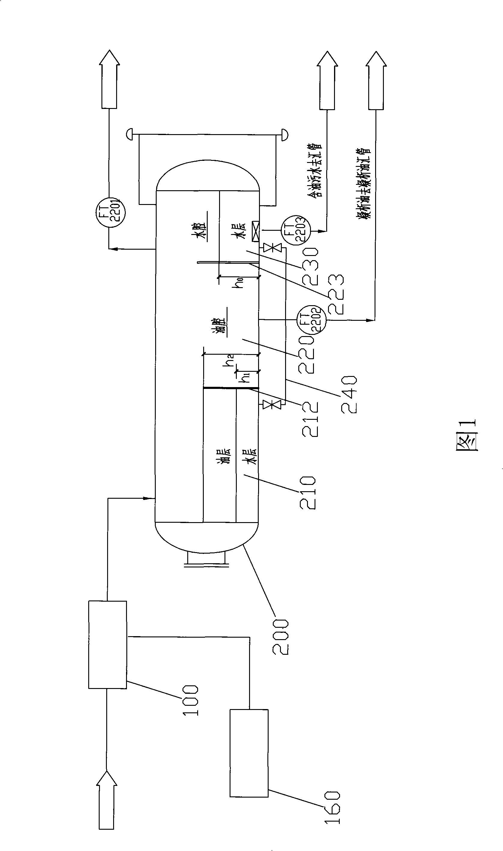
[0026] Please refer to FIG. 1 , which is a schematic flowchart of an embodiment of the oil, gas and water flow measurement system of the present invention. The oil, gas and water flow measurement system is used to measure the flow of oil, gas and water in a single well, which includes: three-phase non-separated flowmeter 100, metering separator 200, gas flowmeter FT2201, oil flowmeter FT2202 and water flowmeter FT2203. The inlet of the three-phase non-separated flowmeter 100 is connected to a single well oil-gas-water mixture pipeline for re...


PUM


Abstract

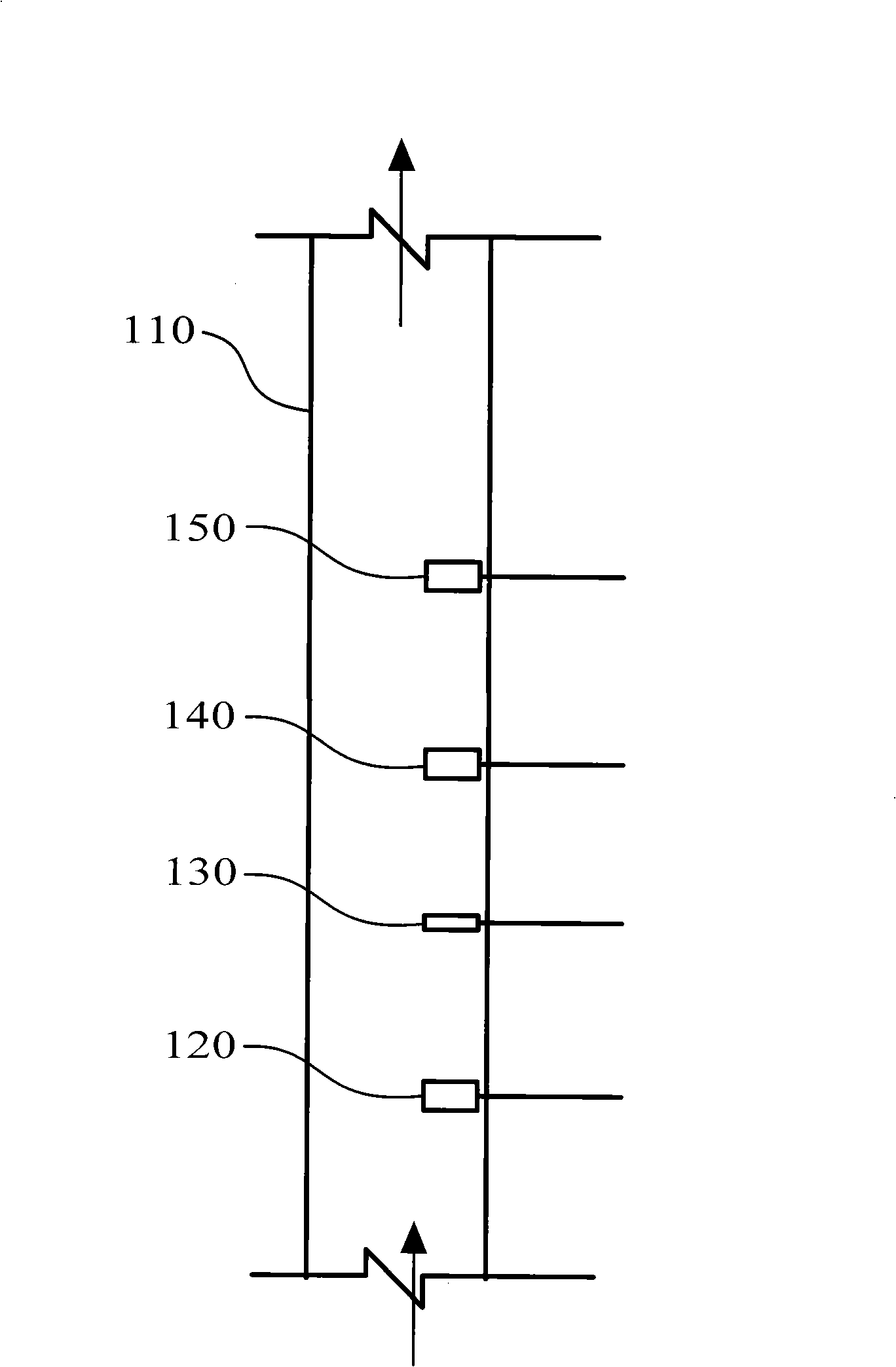
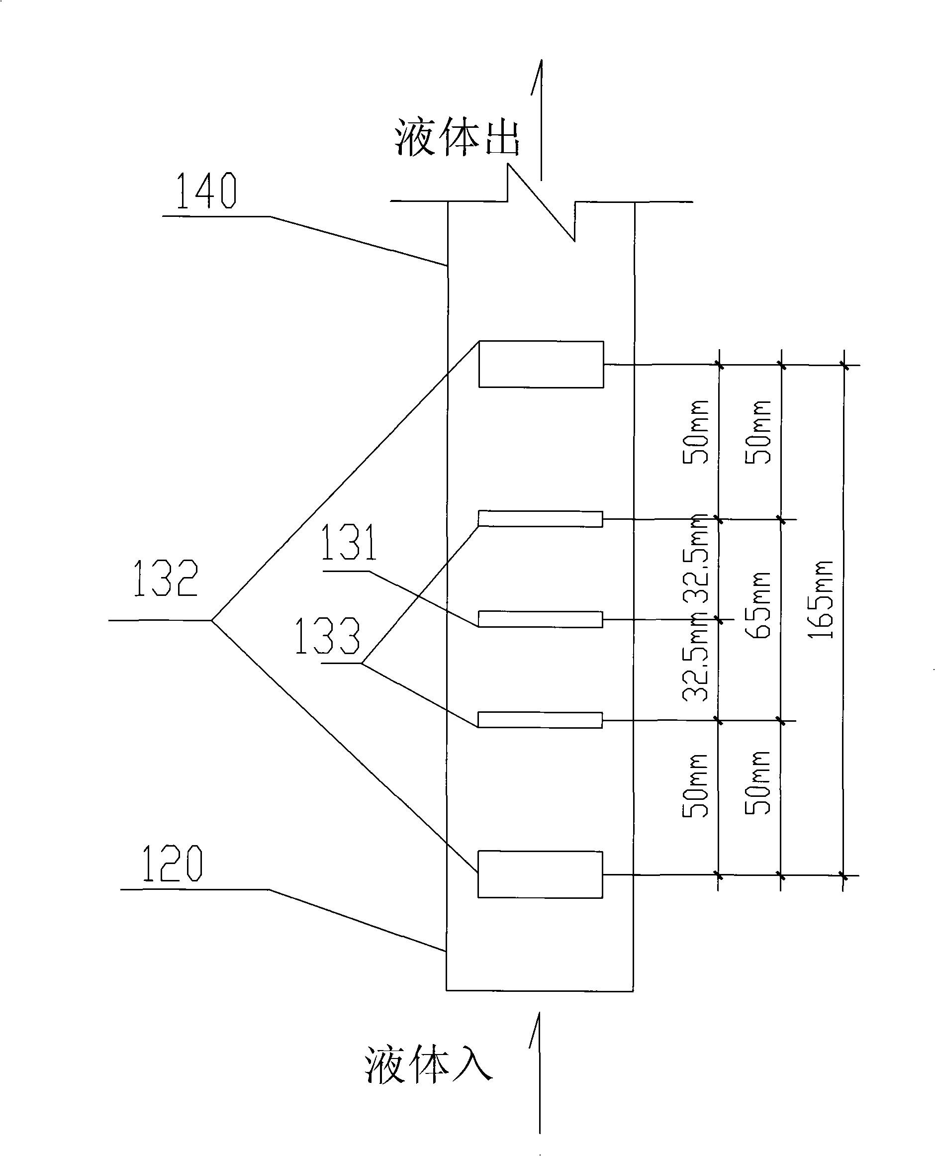
The invention relates to an oil-gas-water flow measurement system which comprises an integrated three-phase flow meter, a metering separator used for the three-phase separation of oil, gas and water, an oil flow meter, a gas flow meter and a water flow meter for the separate metering of oil, gas and water after the separation. The integrated three-phase flow meter includes a main pipe, a venturi device which is arranged on the main pipe and used for measuring the flow of the fluids in the main pipe, a conductivity measuring sensor which is arranged in the main pipe and used for calculating the gas phase fraction of the small gas bubble, the gas phase fractions of oil, gas and water, and the flow rate of the gas and liquid, a capacitance measuring sensor which is arranged in the main pipe and used for calculating the gas phase fractions of the big and small bubbles, the gas phase fractions of oil, gas and water, and the flow rate of gas and liquid and a Gamma densimeter which is arranged in the main pipe and used for calculating the density of the fluids. The oil-gas-water flow measurement system has the advantages of accurately measuring the water content of the condensate oil of the high-pressure condensate gas well, realizing the online monitoring of the oil gas well and becoming more practical.

Description

technical field [0001] The invention relates to a flow measurement system in the field of petroleum exploitation, in particular to an oil-gas-water three-phase flow measurement system. Background technique [0002] At present, during the development of high-pressure condensate gas fields, there has always been the problem that the water content in condensate oil cannot be accurately measured. Condensate gas centralized processing stations usually use gas-liquid separators, flow meters and analytical tests to measure oil, gas and water. Tarim high-pressure condensate gas well has a large gas-oil ratio (2000m 3 / t above), large oil-water density difference (nearly 0.4t / m 3 ) and other characteristics, it is difficult to obtain representative oil-water mixed samples in the existing technological process, and it is impossible to grasp the water content and change trend of a single well, and it is impossible to correctly analyze the dynamic analysis of reservoir development and...

Claims


Application Information

Patent Timeline
Patent Type & Authority Applications(China)
IPC IPC(8): E21B47/00G01F1/44G01P5/08
Inventor 田刚卜志虎吴宗毅
Owner 安东地质工程技术研究院(北京)有限公司
Learn More