Supercharging gasoline engine air administrative system
An air management system and gasoline engine technology, applied in mechanical equipment, combustion engines, machines/engines, etc., can solve the problems of insufficient turbocharged low-speed torque of gasoline engines, and achieve good control of intake air temperature, optimized working conditions, and high boost ratio Effect
- Summary
- Abstract
- Description
- Claims
- Application Information
AI Technical Summary
Problems solved by technology
Method used
Image
Examples
Embodiment 1
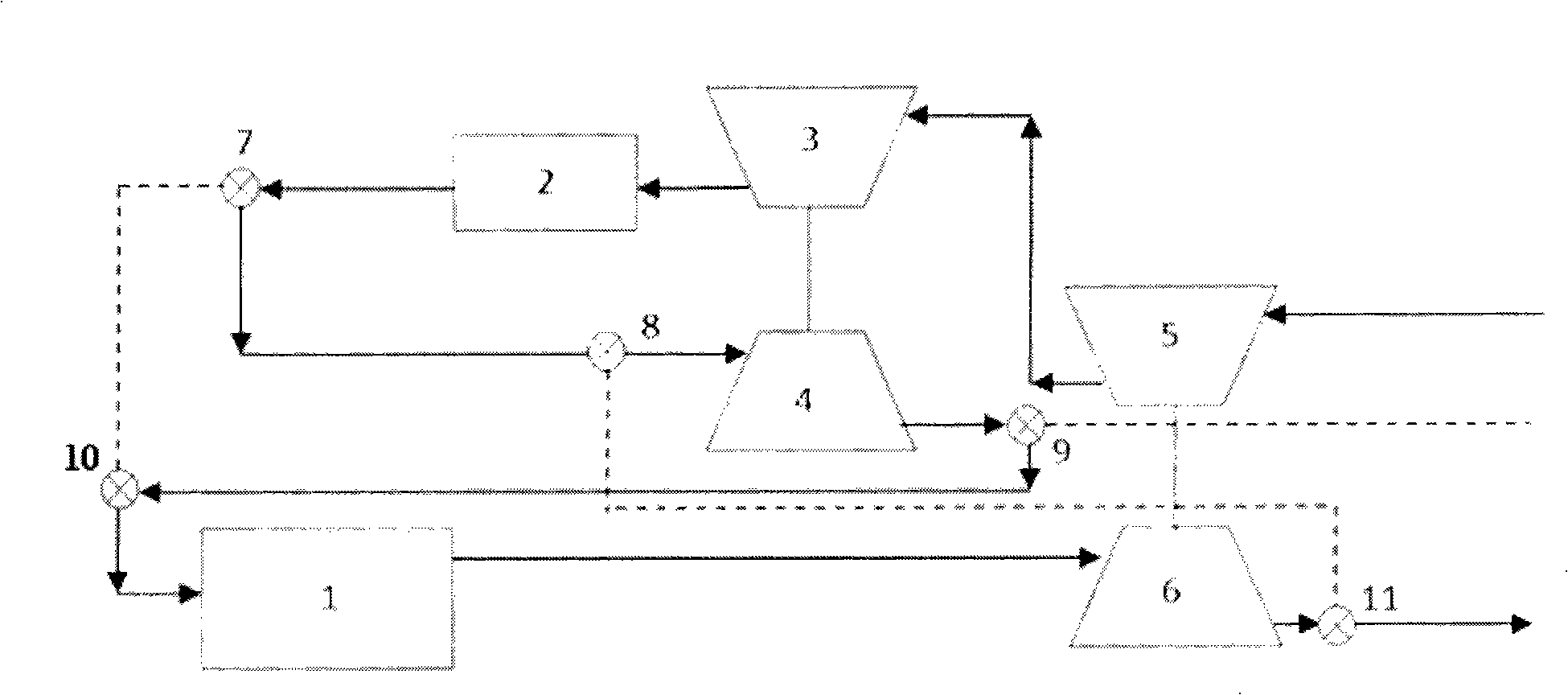
[0016] figure 1 It is a schematic flow chart of the first system of the present invention under medium and high-speed working conditions. The main compressor 5, the double-effect turbine compressor 3, the intercooler 2, the double-effect turbine 4, the cylinder 1 and the main turbine 6 are sequentially connected in series. After the gas is compressed and boosted by the main compressor 5, it enters the double-effect turbo compressor 3 for secondary boost; then enters the intercooler 2, and is cooled by heat exchange with the cooling medium; then the gas passes through the first valve 7 And the second valve 8 enters the double-effect turbine 4, through expansion, the intake air temperature is reduced, and it enters the cylinder 1 through the third valve 9 and the fourth valve 10; after the gas is burned in the cylinder 1, it passes through the main turbine 6 and the second Five valves 11 discharge. When the intake air temperature meets the requirements, the double-effect turbin...
Embodiment 2
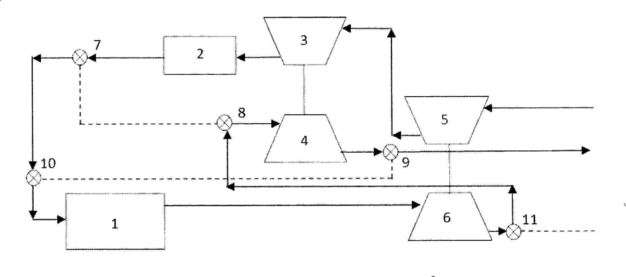
[0018] figure 2 It is a schematic flow chart of the first system of the present invention under low-speed working conditions. The main compressor 5, the double-effect turbine compressor 3, the intercooler 2, the cylinder 1, the main turbine 6 and the double-effect turbine 4 are connected in series in sequence. After the gas is compressed and boosted by the main compressor 5, it enters the double-effect turbo compressor 3 for secondary boost; then enters the intercooler 2, and is cooled by heat exchange with the cooling medium; then the gas passes through the first valve 7 And the fourth valve 10 enters the cylinder 1. After the gas burns in the cylinder 1 and does work, it passes through the main turbine 6. Due to the small gas flow under low-speed conditions, the expansion ratio of the gas at the main turbine 6 is close to 1; then the gas passes through the fifth valve. 11 and the second valve 8, enter the double-effect turbine 4, and the exhaust gas is expanded at the doubl...
Embodiment 3
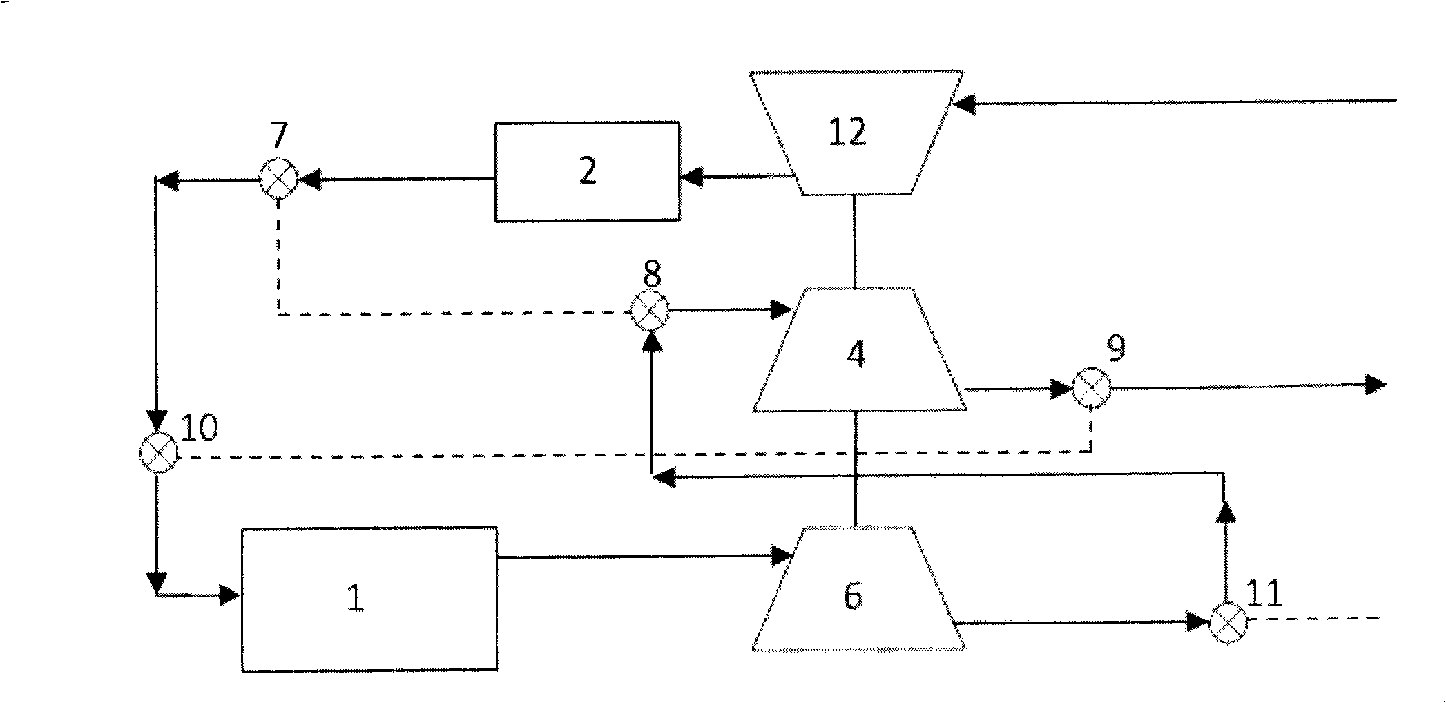
[0021] image 3 It is a schematic flow chart of the second system of the present invention at medium and high speed working conditions, the main compressor 5 and the double-effect turbine compressor 3 are combined into a compressor 12, and the compressor 12 is coaxial with the double-effect turbine 4 and the main turbine 6 Arrangement; compressor 12, intercooler 2, double-effect turbine 4, cylinder 1 and main turbine 6 are connected in series in sequence. After the gas is compressed and boosted by the compressor 12, it enters the intercooler 2 and is cooled by heat exchange with the cooling medium; then the gas enters the double-effect turbine 4 through the first valve 7 and the second valve 8, and expands to make The temperature of the intake air decreases, and it enters the cylinder 1 through the third valve 9 and the fourth valve 10; the gas is discharged through the main turbine 6 and the fifth valve 11 after combustion in the cylinder 1. When the intake air temperature m...
PUM
 Abstract
Description
Claims
Application Information
 - R&D
- Intellectual Property
- Life Sciences
- Materials
- Tech Scout
- Unparalleled Data Quality
- Higher Quality Content
- 60% Fewer Hallucinations
Browse by: Latest US Patents, China's latest patents, Technical Efficacy Thesaurus, Application Domain, Technology Topic, Popular Technical Reports.
© 2025 PatSnap. All rights reserved.Legal|Privacy policy|Modern Slavery Act Transparency Statement|Sitemap|About US| Contact US: help@patsnap.com


