Residual current circuit breaker

A leakage circuit breaker, main circuit technology, applied in the direction of circuits, electrical components, switches operated by ground fault current, etc., can solve the problems of difficult to bend wires, troublesome, soft and damaged insulation tubes, etc.

Active Publication Date: 2008-12-31
FUJI ELECTRIC FA COMPONENTS & SYST CO LTD
View PDF1 Cites 9 Cited by
  • Summary
  • Abstract
  • Description
  • Claims
  • Application Information

AI Technical Summary

Problems solved by technology

Therefore, in the actual product assembly process, the operator uses tweezers or the like to arrange the above-mentioned wires one by one along the prescribed wiring path. This operation consumes labor and time, and the assembly and wiring of the parts The labor cost of operators becomes the main reason for increasing the cost of products
[0014] In addition, an insulating tube is put on each wire such as the stranded wire 15 passing through the primary conductor of the zero-phase converter 5 in advance, or an insulating tape is wrapped for insulation protection, but the insulating tube is soft and easily damaged, so the wiring If it is rubbed against the edges and corners of other metal parts during operation, the tube will be easily damaged
In addition, if an insulating tape (for example, Teflon (Teflon) (registered trademark)) is wound on the wire, the wire itself is difficult to bend, and labor and time are consumed in the wiring operation.
[0015] In addition, in the structure disclosed in Patent Document 1, it is effective from the viewpoint of insulation protection that insulating barriers are provided inside the zero-phase converter to isolate the penetrating primary conductors, but as described above , in a small-capacity earth leakage circuit breaker that uses a flexible twisted wire 15 for penetrating a primary conductor, it is necessary to correct the twisted wire extending from the zero-phase converter 5 to Line 15, secondary output lines, signal lines, etc. are manually sorted one by one, such troublesome operation

Method used


Image

  • Residual current circuit breaker
  • Residual current circuit breaker
  • Residual current circuit breaker

Examples


Embodiment 1

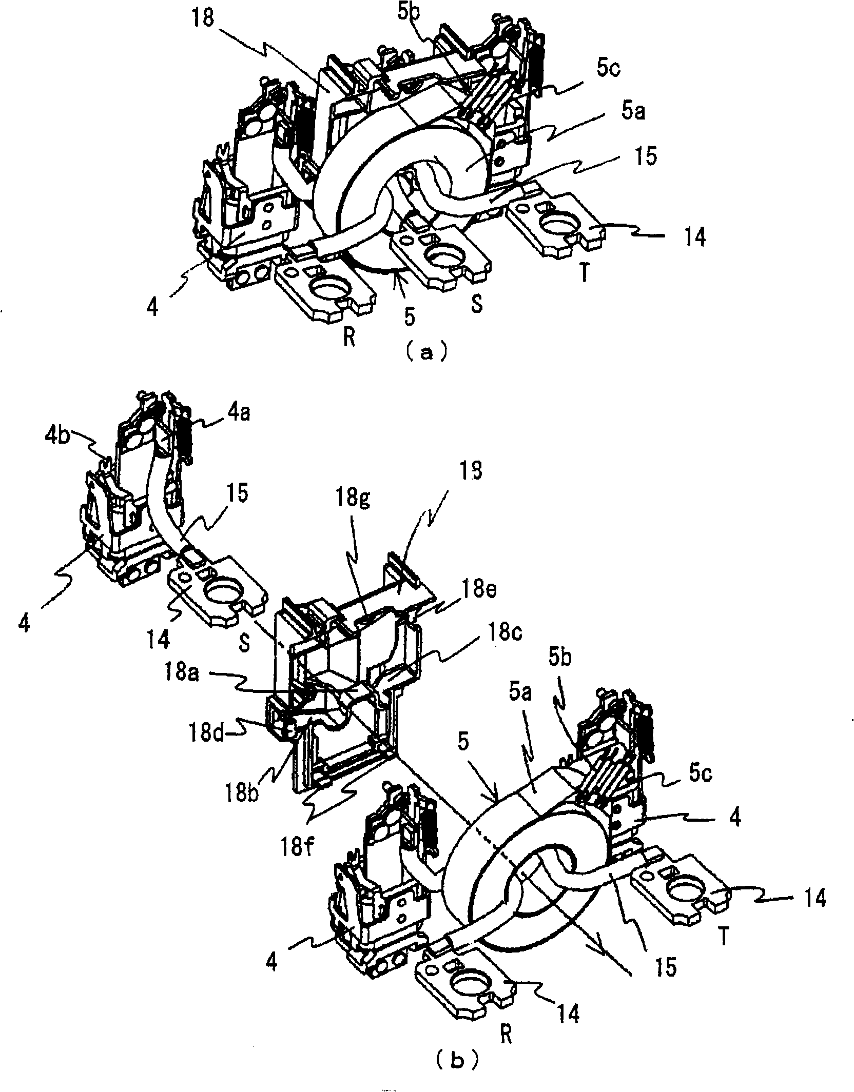
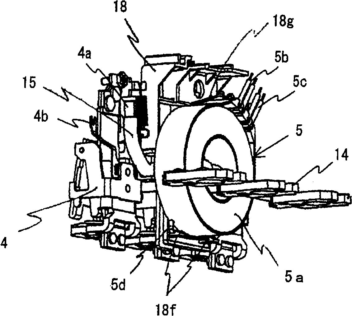
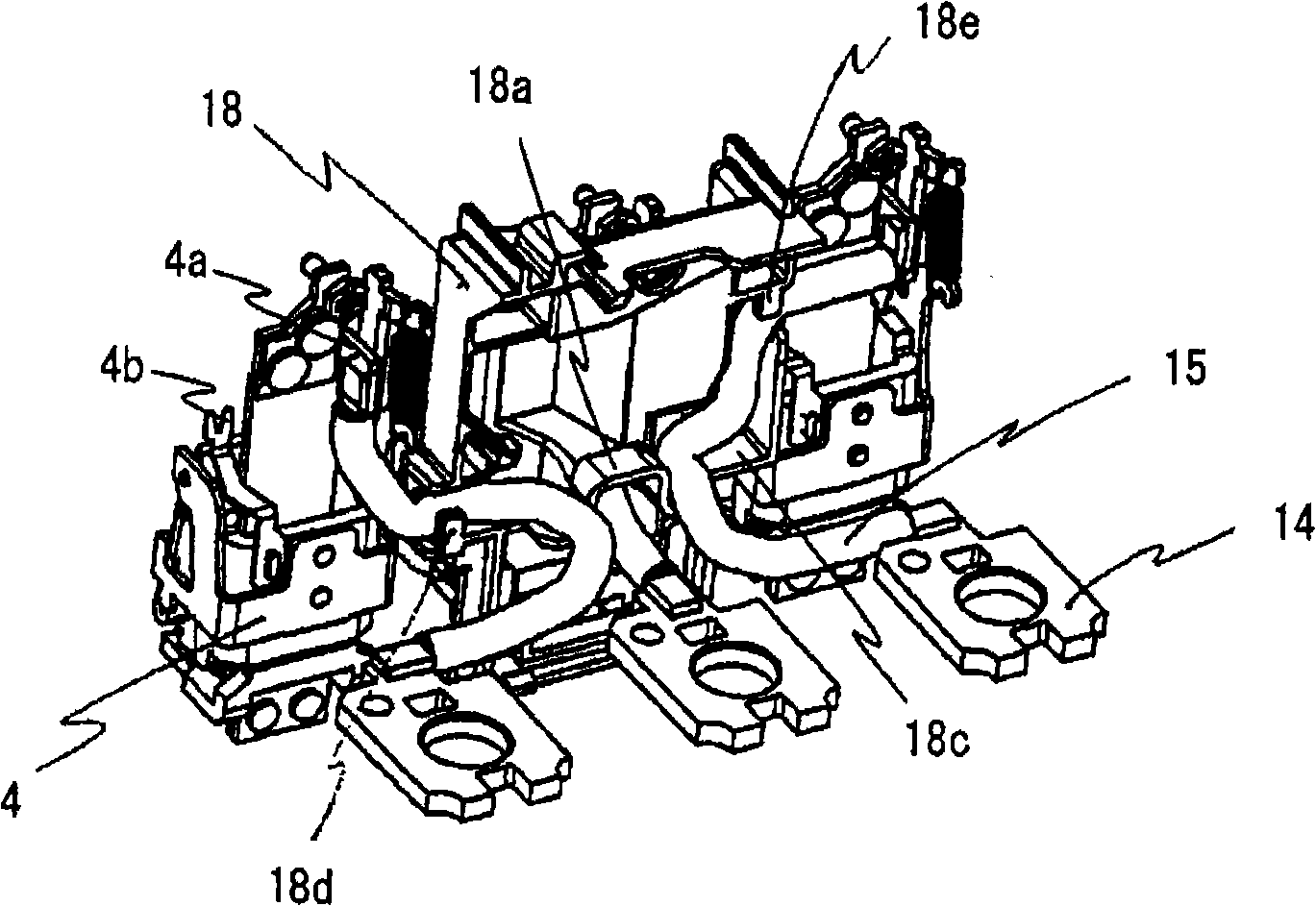
[0065] First, according to Figure 1 to Figure 6 , to explain the working procedure of putting the components and the assembled body of the components into the main body box of the circuit breaker, wherein the above components are combined with the unit of the zero-phase current transformer mounted on the 3-pole earth leakage circuit breaker. Peripheral components such as current trip device and load side terminal. That is, in this embodiment, the unit assembly frame 18 produced by the molded resin molding is prepared as a new part. Then, on the unit assembly frame 18, the structure that the overcurrent release device 4 of each pole is combined with the load side terminal 14 and welded to the two ends of the twisted wire 15 penetrates the zero-phase converter, and as Figure 1 ~ Figure 3 As shown, the zero-phase converter 5 is assembled from components centered on the zero-phase converter. In addition, an insulating tube or an insulating tape (for example, Teflon (registered...

Embodiment 2

[0077] Next, at Figure 7 , Figure 8 The middle shows components of a zero-phase converter mounted on a 4-pole earth leakage circuit breaker applied to a three-phase, four-wire circuit. That is, in this embodiment, the unit assembly frame 18 described in the above-mentioned embodiment 1 is used as a common part, and the zero-phase converter 5, R, S, T phases, and three-phase 4-wire circuit are installed on it. Correspondingly, the stranded wire 15 added as the N-phase (neutral line) through the primary conductor is further combined with the overcurrent release device 4 of each pole and the load-side terminal 14 to form a zero-phase converter 5 as the center. Assembly of components. Here, the twisted wire 15 of the N-phase passes through the zero-phase converter 5 as shown in the figure and is routed and arranged, and the middle part of its wiring path is pressed into the recess 18h of the unit assembly frame 18 (refer to Figure 8 ) and keep it on the frame. In addition, ...


PUM


Abstract

The present invention provides an electric leakage circuit breaker which is a multipole leakage breaker. The inner part of a main case is carried with an opening and closing mechanism for the main circuit connection point, an excess current tripping device, and an electric leakage tripping part which combines an electric leakage detection circuit and a tripping operation coil unit on a null phase current transformer. Flexible stranded wires (15) as the primary conductor of the null phase current transformer (5) are wound between the excess current tripping device (4) of poles and a load terminal (14). The stranded wires of the null phase current transformer and the primary conductor thereof are installed on a unit assembling armature (18) made of casting resin and in are assembled in the main case. The unit assembling armature is provided with guard wall parts between poles (18a), retaining parts for retaining the stranded wires (18b, 18c), retaining sheets for retaining the stranded wires (18d, 18e), stranded wires of the primary conductor keeping through the null phase current transformer along prescribed wire path, and a hasp fitting piece (18f) and an eave shaped fin (18g) for retaining the null phase current transformer (5) at a prescribed position.

Description

technical field [0001] The present invention relates to a leakage circuit breaker suitable for a low-voltage power distribution system. More specifically, the present invention relates to an assembly structure of a zero-phase converter mounted in a leakage circuit breaker and its peripheral components. Background technique [0002] In addition to having the same overcurrent protection function components as the circuit breaker for wiring, the above leakage circuit breaker is also equipped with a zero-phase zero-phase circuit breaker that uses the main circuit as a primary conductor to detect the unbalanced current of the main circuit in the main body box of the circuit breaker. A current transformer, a leakage detection circuit that detects the occurrence of a ground fault based on the secondary output level of the zero-phase current transformer, and a tripping circuit that trips a circuit breaker after receiving an output signal from the leakage detection circuit The leakag...

Claims


Application Information

Patent Timeline
Patent Type & Authority Applications(China)
IPC IPC(8): H01H83/14H01H83/22H01H71/02
CPCH01H83/144H01H83/226H01H83/04H01H83/06
Inventor 浅野久伸
Owner FUJI ELECTRIC FA COMPONENTS & SYST CO LTD
Why Eureka
Try Eureka