Image stabilizer

A technology for jitter correction and actuator, applied in the directions of printing equipment, projection equipment, installation, etc., can solve the problems of low detection accuracy of the position of the camera element, easy overlap of the error amount, etc., and achieve the effect of ensuring miniaturization and reducing the amount of error

Inactive Publication Date: 2008-12-31
OLYMPUS CORP
View PDF1 Cites 13 Cited by
  • Summary
  • Abstract
  • Description
  • Claims
  • Application Information

AI Technical Summary

Problems solved by technology

[0004] However, in the device described in Patent Document 1, the position detection sensor is arranged on the outer side of the position where the actuator is arranged, so the shake correction device is enlarged.
In addition, since the position detection sensor is separated from the imaging element, the error amount tends to overlap and the position detection accuracy of the imaging element decreases.

Method used


Image

  • Image stabilizer
  • Image stabilizer
  • Image stabilizer

Examples


Embodiment Construction

[0033] Hereinafter, the best mode for implementing the shake correction device of the present invention will be described with reference to the drawings. The camera shake correction device of this embodiment is a camera shake correction device for correcting hand shake of an imaging unit including an image pickup element that obtains an image signal through photoelectric conversion. example to illustrate.

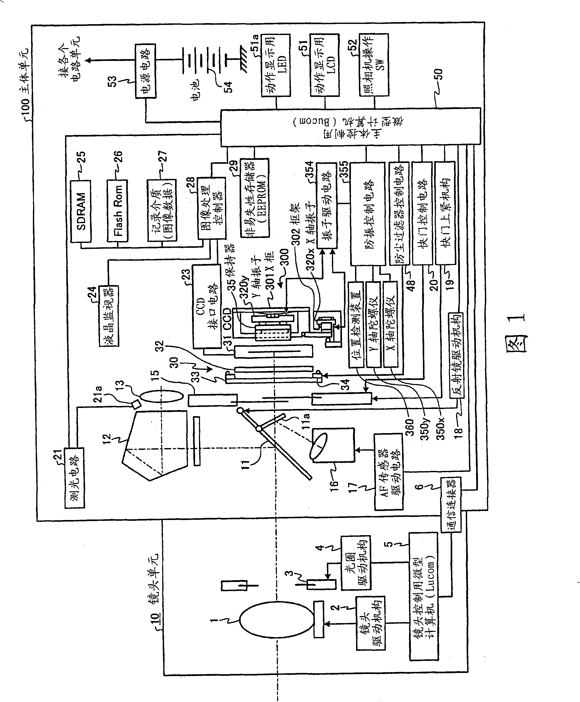
[0034] First, a system configuration example of an electronic camera equipped with the shake correction device according to the present embodiment will be described with reference to FIG. 1 . FIG. 1 is a block diagram schematically showing the main electrical system configuration of an electronic camera. This electronic camera constitutes a system by a main body unit 100 which is a camera body, and a lens unit 10 which is an interchangeable lens which is one of accessory devices.

[0035]The lens unit 10 is detachable via an unillustrated lens mount provided on the front ...


PUM


Abstract

The present invention provides a shake correcting device, which can ensure the device miniaturization and accurately detect the relative position of a camera shooting element. An X-axis actuator (320x) and a Y-axis actuator (320y) are arranged near respective positions of fictitious intersection points (P) at length directional axis (Lx, Ly) but not intersection, a position detecting component for detecting the relative position of CCD(31) is arranged in areas (E) containing fictitious intersection points (P) and surrounded by each one end of the X-axis actuator (320x) and the Y-axis actuator (320y), thus the device can be ensure miniaturization by a dead space generated by the arrangements of the X-axis actuator (320x) and the Y-axis actuator (320y). Furthermore, the present invention can reduce error quantity by arranging the position detecting component near the position of CCD(31), and accurately detect the relative position of CCD(31).

Description

technical field [0001] The present invention relates to a shake correction device for correcting hand shake in an imaging device such as a digital camera. Background technique [0002] Conventionally, in an imaging device, there is a shake correction device that uses an actuator (actuator) to make an imaging element such as a CCD independent in the horizontal direction and the vertical direction in a plane perpendicular to the imaging optical axis in order to correct the hand shake. The position of the subject light beam formed on the imaging plane of the imaging element is corrected by shifting the ground (for example, refer to Patent Document 1). In this case, in order to control the driving amount of the actuator, it is necessary to have a position detection sensor that detects the relative position of the imaging element that is displaced and moved. Here, in Patent Document 1, the position detection sensor is disposed outside the actuator that operates the imaging devic...

Claims


Application Information

Patent Timeline
Patent Type & Authority Applications(China)
IPC IPC(8): H02N2/00G02B7/04
CPCG02B27/646G03B5/00H04N23/54H04N23/68
Inventor 川合澄夫
Owner OLYMPUS CORP
Why Eureka
Try Eureka