Evaporative cooling device

An evaporative cooling, plate technology, applied in natural cooling systems, energy-saving heating/cooling, heating methods, etc., can solve problems such as affecting temperature differences and disadvantages

Active Publication Date: 2008-12-31
OXYCOM BEHEER BV
View PDF7 Cites 17 Cited by
  • Summary
  • Abstract
  • Description
  • Claims
  • Application Information

AI Technical Summary

Problems solved by technology

It should also be noted in this technical background that heat transfer along the membrane is not required as it can adversely affect the temperature difference between the inlet and outlet

Method used


Image

  • Evaporative cooling device
  • Evaporative cooling device
  • Evaporative cooling device

Examples


Embodiment Construction

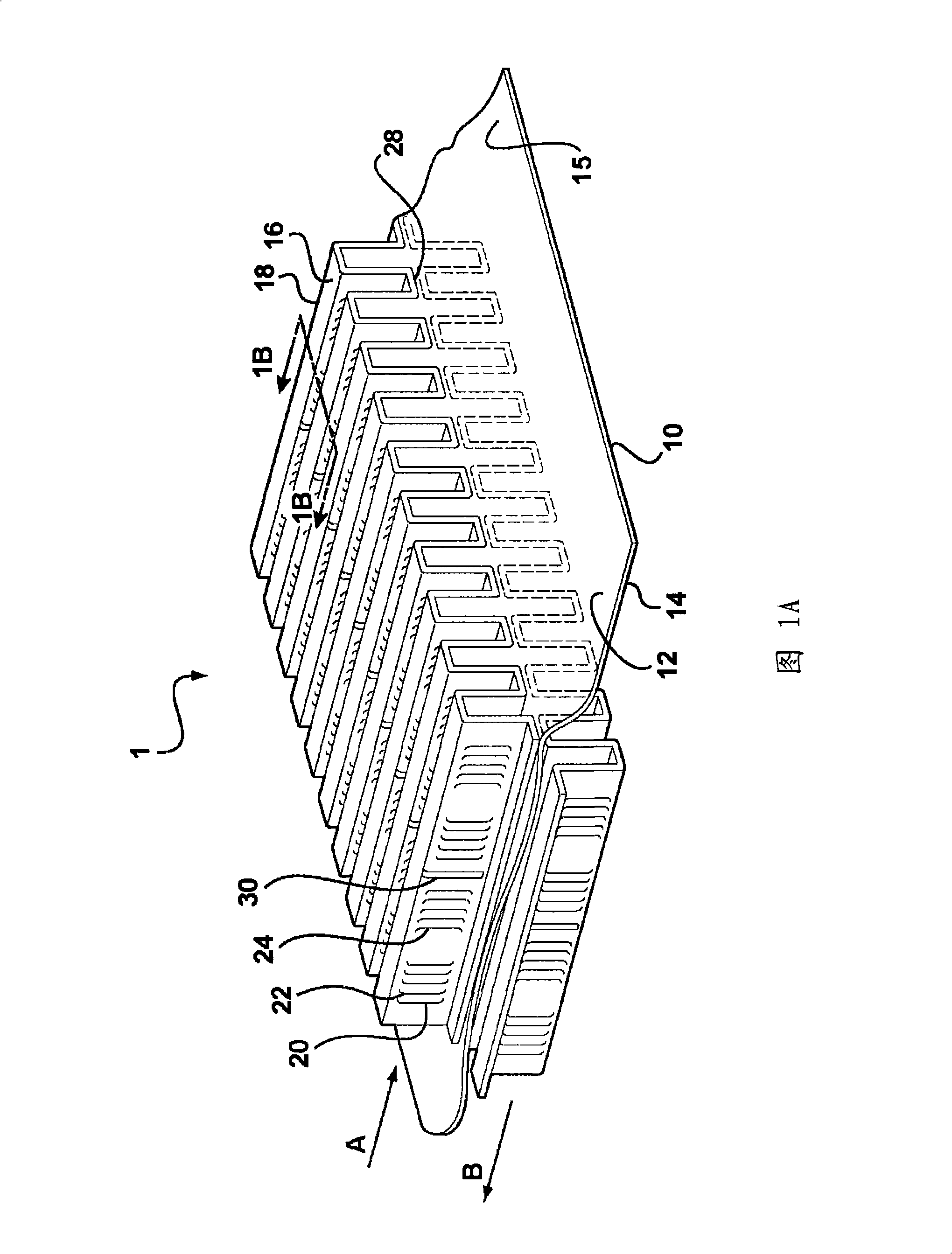
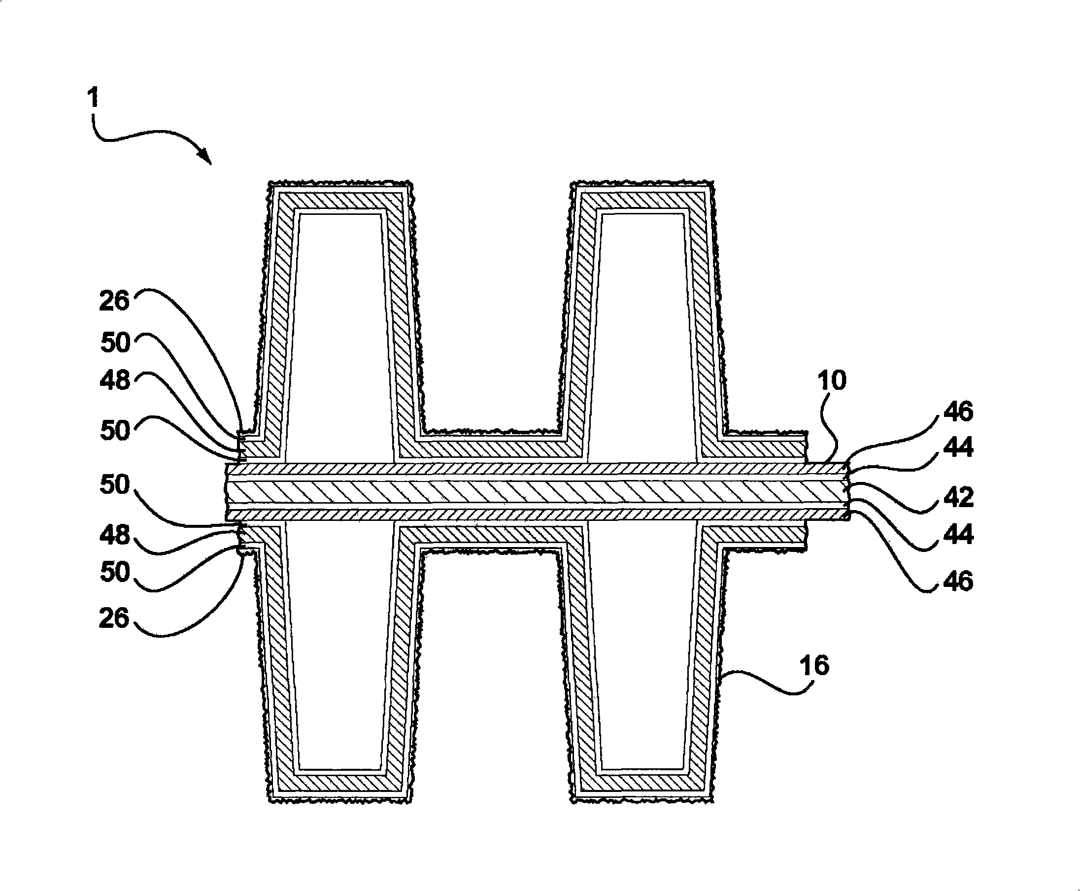
[0032] Figure 1A shows a part of a heat exchange element 1 of the type currently used in the prior art heat exchanger described in PCT Publication WO04 / 040219, the content of which is hereby incorporated by reference. The heat exchange element 1 comprises a membrane 10 having a first surface 12 and a second surface 14 . Arrows A and B indicate the flow direction of air for use as a dew point cooler. Arrow A represents the main air flow over the first surface 12 . Arrow B represents the secondary air flow over the second surface 14 . The membrane 10 is formed from a thin aluminum plate. Both sides of the membrane 10 are provided with flaps 16 arranged in strips 18 . The flaps 16 are attached to the film 10 at their bases 28 by heat seal adhesive. For this purpose, the tab 16 is also formed from aluminum laminated with a heat seal adhesive. In this type of evaporative cooling device, the heat exchange mainly takes place on the surface of the fins 16 on the second surface 14...


PUM


Abstract

A evaporative cooling device is described having a pair of heat conducting plates (102) arranged in spaced, generally parallel relationship with spacing elements (104) separating the plates (102) from one another and defining primary (l06)and secondary (108) flow channels between the plates. Inlet ducts (114) are connected to the primary (106) channels and outlet ducts connect from the primary (106) and secondary (108) channels. A water distribution system (116) is also provided to supply water to the secondary (108) channels such that a primary air flow (A) through the primary (106) channels may be cooled by heat conduction along the plates (102) to cause evaporation of the water into a secondar air flow (B) throuh the secondary (108) channels.

Description

technical field [0001] The present invention relates to heat exchange devices, and more particularly to evaporative cooling devices of the type capable of cooling a primary or product air stream by evaporating fluid into a secondary or working air stream. Such devices may also operate to provide heat recovery as well as ventilation. Background technique [0002] An evaporative cooler is a device that uses the latent heat of evaporation of a liquid to provide cooling. The principles of evaporative cooling have been known for many centuries. For example, a damp cloth placed on an object will keep the object cool by evaporating liquid from the cloth. By continuously adding liquid to the cloth, the cooling effect can be maintained indefinitely without the need for electrical input. The lowest temperature that can be achieved by evaporating moisture into an air stream in this way defines the wet bulb temperature of that air. Indirect evaporative coolers utilize this principle...

Claims


Application Information

Patent Timeline
Patent Type & Authority Applications(China)
IPC IPC(8): F28D5/00F24F1/0076
CPCF24F5/0035F28D5/00F28F3/025F28F13/02F28F2245/02F28D9/0037F28D9/0062F28F3/086F28F2250/104F24F1/0007Y02B30/54F24F1/0076
Inventor 保罗·M·克拉克森安德烈亚斯·J·L·尼杰森约翰尼斯·A·M·赖恩德斯
Owner OXYCOM BEHEER BV
Why Eureka
Try Eureka