Thermal treatment apparatus

a technology of thermal treatment apparatus and thermal treatment apparatus, which is applied in the direction of lighting and heating apparatus, drying machines with progressive movements, furnaces, etc., can solve the problems of increasing the amount of thermal energy that must be supplied to the thermal treatment apparatus, reducing the effective heat efficiency, and reducing the effective heat efficiency. , to achieve the effect of reducing the total thermal energy consumed in the thermal treatment apparatus, reducing the heat loss, and saving operation energy

Inactive Publication Date: 2003-09-23
PANASONIC CORP
View PDF9 Cites 15 Cited by
  • Summary
  • Abstract
  • Description
  • Claims
  • Application Information

AI Technical Summary

Benefits of technology

The present inventors have intensively studied about the heat loss. Through the study, it has been found that, of the heat released from the water that flows through the cooling water pipe in the muffle furnace described above, heat corresponding to about 25 to 45% of the input thermal energy is caused by the thermal conduction from the muffle wall that defines the heating zone to the muffle wall that defines the cooling zone. The present inventors have completed the thermal treatment apparatus of the present invention that involves a smaller heat loss than that of the prior art by providing the thermal treatment apparatus with means for effectively suppressing the thermal conduction.
Moreover, the thermal insulating structural member and the thermal blocking plate member can suppress the thermal conduction between the two adjacent thermal treatment chambers without allowing the atmosphere gas in the thermal treatment chambers to leak to the outside of the thermal treatment chambers. Therefore, the thermal treatment apparatus of the present invention can stably apply a thermal treatment to the object to be treated with a higher effective heat efficiency without disturbing the atmosphere gas in the thermal treatment chambers.

Problems solved by technology

In the muffle furnace described above, there is such a problem that only a very small part of the thermal energy supplied by the heater (9) is utilized for heating the object to be treated, namely an effective heat efficiency is very low.
The lower the effective heat efficiency, the larger the amount of thermal energy that must be supplied to the thermal treatment apparatus.
This results in a higher running cost of the thermal treatment apparatus and leads to an increase in the product cost.
The released heat does not reach the object to be treated, and therefore entirely amounts to heat loss.
All the heat released in this manner amounts to heat loss.
As a result, the carrier tends to be large in size, and the heat capacity of the carrier inevitably becomes large accordingly.
Consequently, when the carrier is cooled down, a large amount of heat stored in the carrier is released.
However, since the thermal energy released from the carrier has been supplied thereto merely for the purpose of maintaining the constant temperature around the object in the heating zone, it constitutes the heat loss.
However, the rest of the heat has not been closely studied with regard to the transfer path thereof.

Method used


Image

  • Thermal treatment apparatus
  • Thermal treatment apparatus
  • Thermal treatment apparatus

Examples


example 1

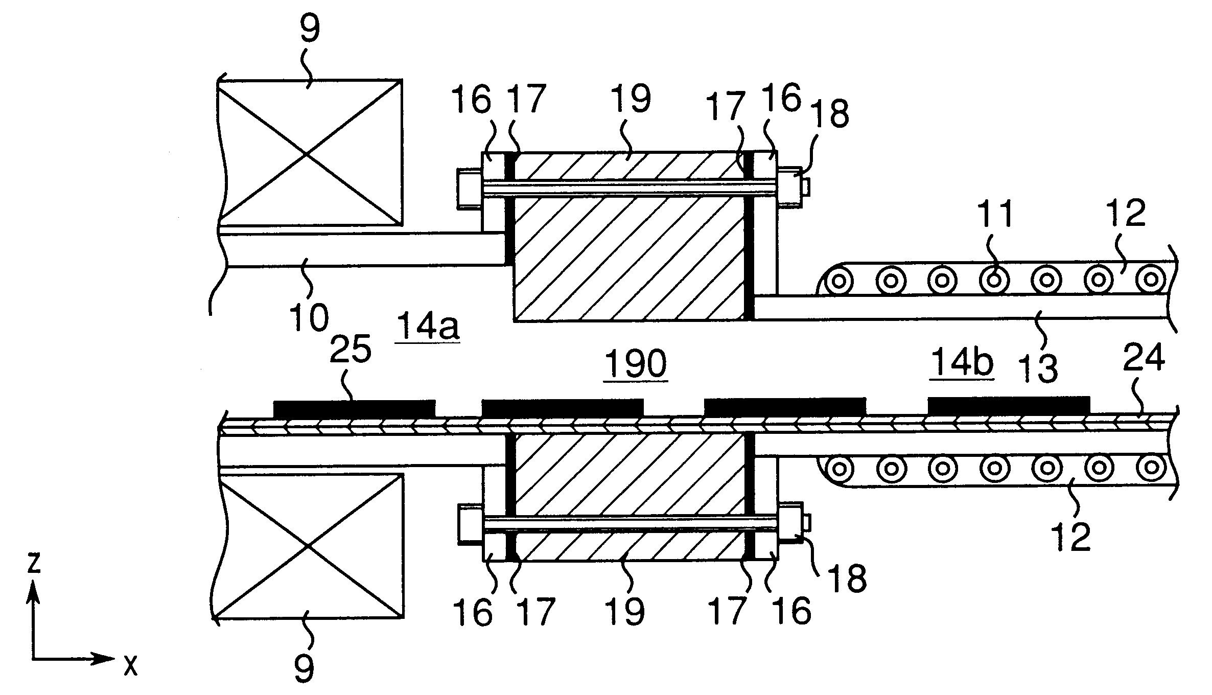
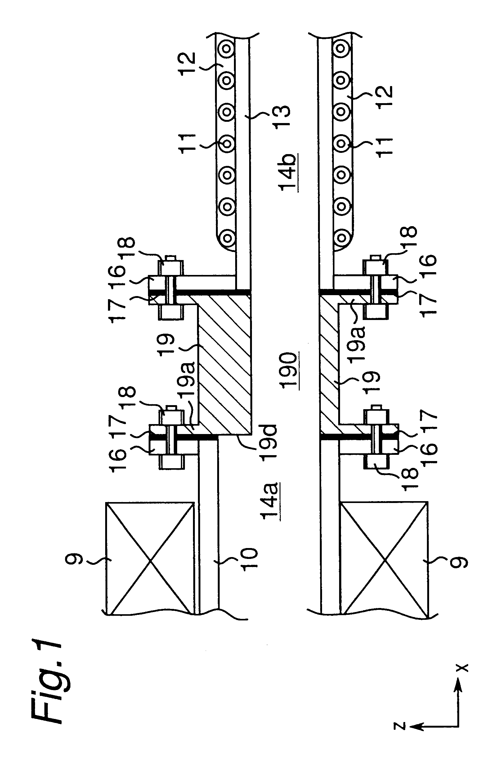
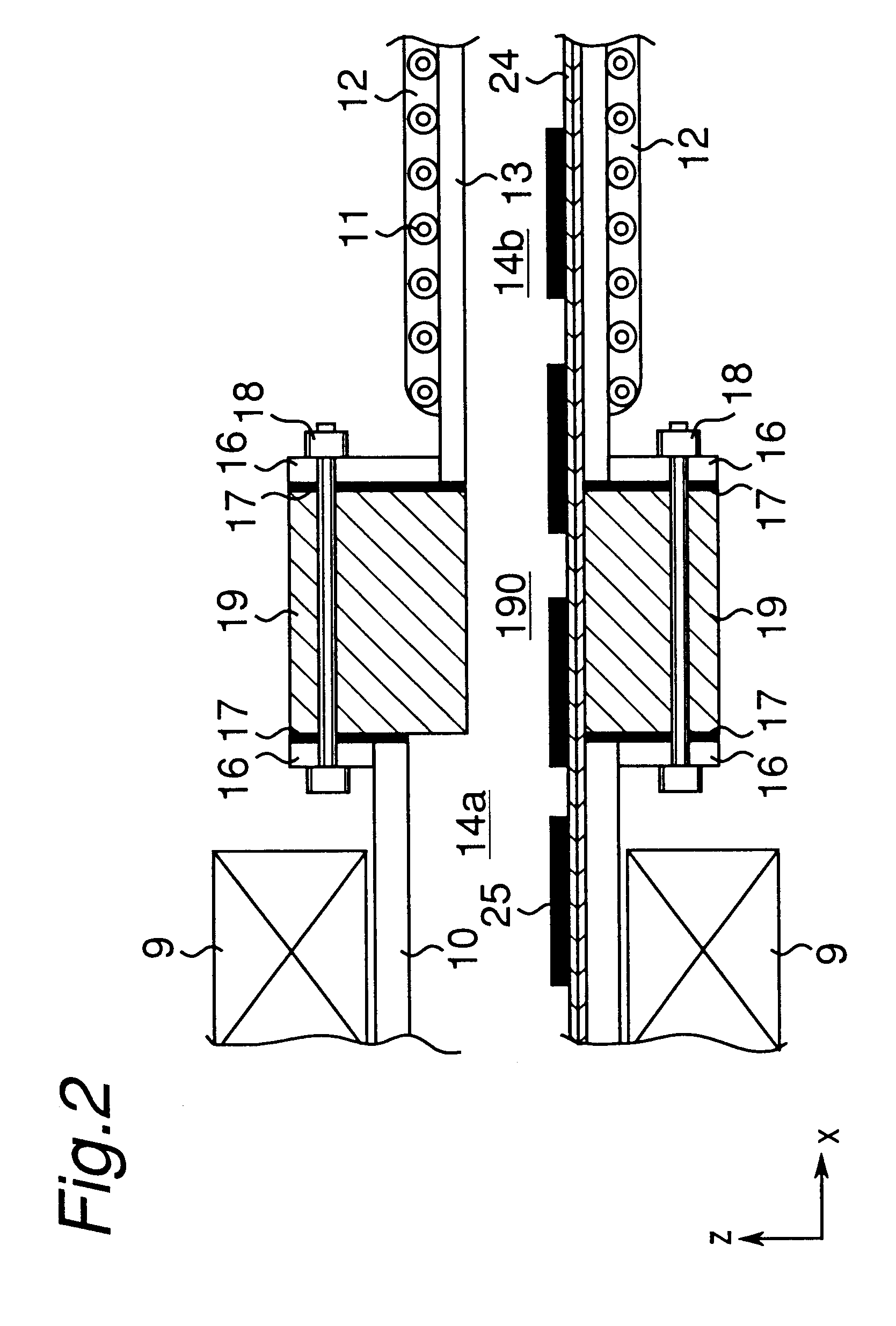
A thermal treatment apparatus having one heating muffle and one cooling muffle was constructed. In the thermal treatment apparatus, a thermal insulating structural member formed of a wall made of a material of low thermal conductivity was disposed between the heating muffle and the cooling muffle as shown in FIG. 2.

Materials and sizes of the heating muffle (10), the cooling muffle (13), the mesh belt (24), the object (25) to be treated and the thermal insulating structural member (19) in this Example are as follows.

1) Heating muffle

Material was Inconel 600 of which thermal conductivity at normal temperature was 14.8 W / m.multidot.K;

Wall thickness was 10 mm;

Configuration of muffle was a tubular shape having a semicircular cross section in which an upper wall is arched, with a flange welded to the end face as a joint member;

Width, maximum height and length of muffle were 1000 mm, 250 mm and 7000 mm, respectively; and

Cross section of the thermal treatment zone was a semicircular shape w...

example 2

A thermal treatment apparatus was constructed by providing the thermal insulating structural member formed of a thin plate between the heating muffle and the cooling muffle as shown in FIG. 6. The heating muffle and the cooling muffle of the thermal treatment apparatus of Example 2 are the same as those of Example 1.

In this Example, a stainless steel sheet of 1.0 mm thick was employed as the thin plate. With this thin plate, the thermal insulating structural member (21) was formed into a construction having a hollow of rectangular cross section and a length of 100 mm. A connecting member (22) made of stainless steel plate was used to connect the thermal insulating structural member and the muffle. The thin plate constituting the thermal insulating structural member (21) was fixed to the connecting member (22) by welding.

example 3

Such a thermal treatment apparatus was constructed as the thermal blocking plate member (26) was disposed between the joint member (30) of the heating muffle and the connecting member, (22) of the thermal insulating structural member as shown in FIG. 9 in the thermal treatment apparatus of Example 2. The heating muffle, the cooling muffle and the thermal insulating structural member of the thermal treatment apparatus of Example 3 are the same as those of Example 2. A stainless steel sheet having thickness of 1.0 mm and surface thermal emissivity of 0.01 was used as the thermal blocking plate member (26). In the thermal blocking plate member, an aperture (29) having a height of 25 mm and a width of 980 mm was formed so as to allow the mesh belt (24) and the object to be treated (25) to pass therethrough as shown in FIG. 10A.


PUM

PropertyMeasurementUnit
temperaturesaaaaaaaaaa
temperatureaaaaaaaaaa
temperaturesaaaaaaaaaa

Abstract

A thermal treatment apparatus has a plurality of thermal treatment chambers in which an object to be treated is thermally treated while being transported, and at least one pair of two adjacent thermal treatment chambers of which inside temperatures are different from each other. The thermal treatment chambers are connected through a thermal insulating structural member, whereby thermal conduction between the chambers, such as muffles, is prevented to reduce a heat loss caused in the thermal treatment apparatus. Therefore, input thermal energy which is necessary to carry out a predetermined thermal treatment is significantly reduced without affecting quality and yield of the object.

Description

The present invention relates to a thermal treatment apparatus used for a thermal treatment of a starting material, an intermediate product or a final product.Various thermal treatment processes such as a heating process and a cooling process are employed in the processes of manufacturing various products such as a plasma display panel, a solar battery panel, a resistor chip and other devices and electronic parts. Numerous effects achieved by a thermal treatment are known. Specifically, drying, dehydration, calcination, reaction acceleration, surface modification, sealing, degassing, annealing and so on are known.In a case where a heating furnace is used as a thermal treatment apparatus, the thermal treatment apparatus generally has a plurality of thermal treatment chambers arranged in the direction of transporting an object to be treated. Each thermal treatment chamber has a space provided therein in which the object is subjected to a thermal treatment, namely a thermal treatment z...

Claims


Application Information

Patent Timeline
Patent Type & Authority Patents(United States)
IPC IPC(8): F26B15/10F26B25/06F26B25/08F26B15/00F27B9/26F27B9/02F27B9/08F27D1/14F27B9/00H01L21/00F27D1/00
CPCF26B15/10F26B25/08F27B9/028F27B9/08F27B9/26F27D1/145H01L21/67103C03B35/14C03B25/08C03B29/08F27D2001/0069H01L21/324
Inventor TSUTSUI, YUJINAKA, HIROYUKI
Owner PANASONIC CORP
Why Eureka
Try Eureka