Control of rotating field machine

A technology of rotating field and control equipment, applied in the field of feedback control, which can solve the problems of electric power reduction of rotating field motors, problems of heat export, and temperature rise of series resistance

Inactive Publication Date: 2016-07-27
ZF FRIEDRICHSHAFEN AG
View PDF9 Cites 4 Cited by
  • Summary
  • Abstract
  • Description
  • Claims
  • Application Information

AI Technical Summary

Problems solved by technology

However, the series resistor may heat up during operation, wherein the power converted to it rises quadratically with the current flowing th

Method used


Image

  • Control of rotating field machine
  • Control of rotating field machine

Examples


Embodiment Construction

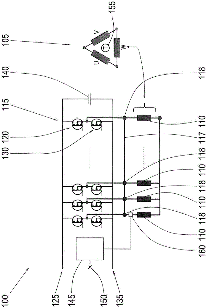
[0016] figure 1 A circuit diagram of the components of a control device 100 for controlling a rotating field motor 105 is shown. The rotating field machine 105 can be used in particular in a motor vehicle, for example as a generator, starter or in particular as an integrated starter generator. The rotating field electric machine 105 generally comprises P phases, of which three phases U, V and W are exemplified here. Each phase comprises a plurality of windings 110 which are connected in parallel to one another and are preferably constructed identically. exist figure 1 In the illustration of , only the components relating to phase W are shown in more detail, the other phases U and V being driven in a corresponding manner.

[0017] A half-bridge 115 is provided to provide a predetermined voltage at the connections of the phase W. Half-bridge 115 includes a first current valve 120 for connecting the terminal to high potential 125 and a second current valve (“low-side switch”)...


PUM


Abstract

The invention relates to control of a rotating field machine. The rotating field machine comprises a plurality of phase and each phase includes a plurality of parallel windings. The invention also relates to a control device used for the rotating field electric machine. The device used for the rotating field electric machine comprises a half-bridge for each phase, a processing device for controlling the half bridge according to phase current passing through one of the phases, and a current sensor. The current sensor is set as winding current for flowing through one of the windings of the phase and the processing device is configured to determine phase current on the basis of the winding current.

Description

technical field [0001] The invention relates to the control of rotating field electric machines. In particular, the invention relates to feedback control of rotating field machines. Background technique [0002] A rotating field machine can alternatively be used as a motor or as a generator. In a drive train of a motor vehicle, the rotating field machine can be used, for example, for driving or for recuperating electrical energy during braking of the motor vehicle, as required. In a further embodiment, the rotating field machine can be used as an integrated starter generator alternatively for starting the internal combustion engine or for converting mechanical energy from the drive train into electrical energy, for example as an on-board electrical system of a motor vehicle. Rotating-field electric machines can include, in particular, electrically excited or permanent-magnet synchronous machines, reluctance machines, asynchronous machines or combinations of these machine t...

Claims


Application Information

Patent Timeline
IPC IPC(8): H02P25/22H02P27/06
CPCH02P25/22H02P27/06H02K11/27H02P2207/01
Inventor 汉斯-于尔根·汉夫特埃里克·卡格阿尔弗雷德·塔雷卢斯
Owner ZF FRIEDRICHSHAFEN AG
Why Eureka
Try Eureka