
Binary graphitization furnace

A graphitization furnace and furnace body technology, applied in the chemical industry, sustainable manufacturing/processing, climate sustainability, etc., can solve the problem of large power consumption, long cooling time of the furnace body, and low energy utilization rate of a single graphitization furnace problems such as improving energy utilization, shortening production time, and clear device structure

Active Publication Date: 2016-05-11
SHANXI BEITERUI NEW ENERGY TECH
View PDF2 Cites 4 Cited by
  • Summary
  • Abstract
  • Description
  • Claims
  • Application Information

AI Technical Summary

Problems solved by technology

[0005] 1. Due to the large power consumption and large heat loss of the single graphitization furnace, the energy utilization rate is low and the cost is relatively high
[0006] 2. The monomer graphitization furnace is limited by the process conditions, adopts natural cooling method, the cooling time of the furnace body is long, and the production interval is also long

Method used


Image

  • Binary graphitization furnace
  • Binary graphitization furnace

Examples


Embodiment Construction

[0019] Specific embodiments of the present invention will be described in detail below in conjunction with the accompanying drawings.

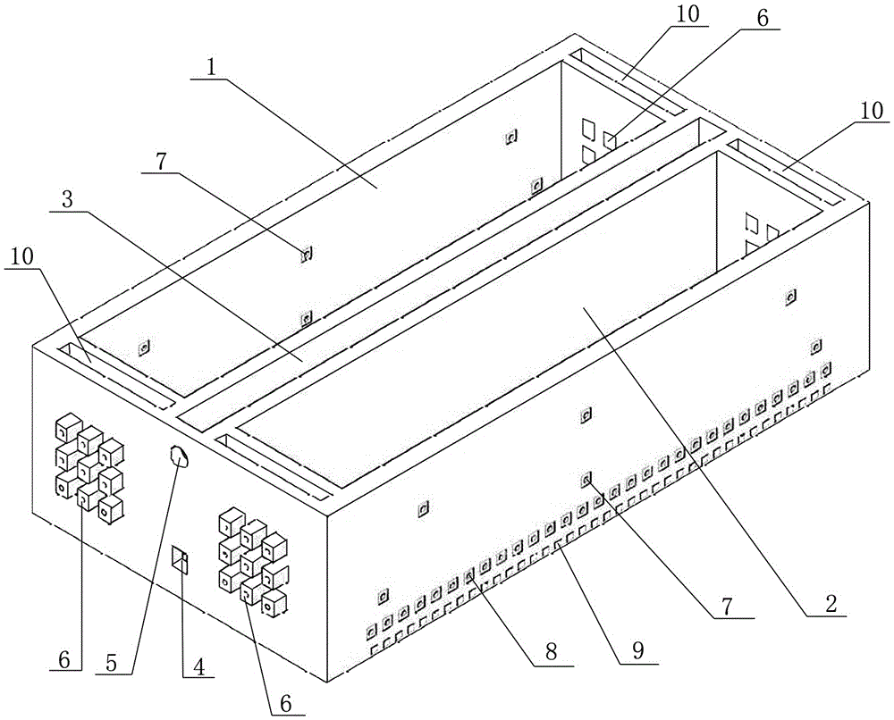
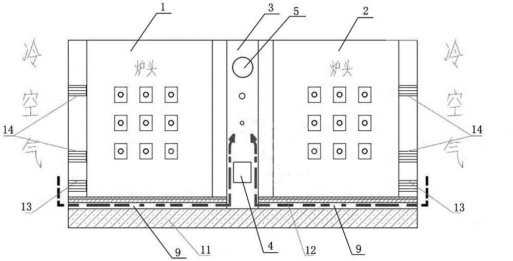
[0020] A two-body graphitization furnace, such as figure 1 As shown, it includes the first furnace body 1 and the second furnace body 2 arranged in parallel, the middle combined part of the first furnace body 1 and the second furnace body 2 forms a waste heat flue space 3, and the waste heat flue space is divided into upper and lower Two layers, the lower flue is connected to the inner lower ventilation duct at the bottom of the two furnace bodies, the heat from the bottom of the furnace enters the flue from the air duct during cooling, and a circulating water pipe is set in the waste heat flue space 3, and the circulating water pipe is located at The inlet 4 on the front side of the middle composite part is connected to the front, and the outlet 5 is connected to the outlet; in the middle composite part of the two parallel graphitization kiln...


PUM


Abstract

The invention relates to the technical field of graphite preparation, in particular relates to a binary graphitization furnace which is combined by adopting a parallel connection way. The binary graphitization furnace comprises a first furnace body (1) and a second furnace body (2), wherein a middle combination part of the first furnace body (1) and the second furnace body (2) forms waste heat flue space (3); a circulating tube is arranged in the waste heat flue space; the circulating pipe enters the waste heat flue space (3) from an inlet (4) formed in the front surface of the middle combination part and stretches out of the waste heat flue space (3) from an outlet (5) formed in the front surface of the middle combination part; an axial flow fan is arranged at the position of the outlet of the waste heat flue space (3). The binary graphitization furnace disclosed by the invention is reasonable in design; compared with an existing graphitization furnace kiln, the actual effects of high heat efficiency, good safety, capability of implementing forced cooling and the like are obtained; meanwhile, the binary graphitization furnace is clear in structure and energy-saving purpose, has very good practical performances of safety, easiness in operation and the like and has very obvious economic benefit after implementation.

Description

technical field [0001] The present invention designs the technical field of graphite preparation, specifically a two-body graphitization furnace combined in parallel. Background technique [0002] Traditional high-temperature ventilated graphitization furnaces (referred to as Acheson graphitization furnaces) all adopt the single furnace method. This design method has better flexibility, and the production is easy to deploy and control. [0003] The general process route of the graphitization kiln is: pre-loading operations (canning, kiln maintenance, laying ventilation pipes, filling the bottom of the furnace, etc.) ---- Furnace loading ---- Power transmission (ventilation) ---- Overall cooling----out of the oven----finished product cooling----packing. [0004] However, the monomer graphitization furnace has the following problems: [0005] 1. Due to the large power consumption and large heat loss of the single graphitization furnace, the energy utilization rate is low an...

Claims


Application Information

Patent Timeline
IPC IPC(8): C01B31/04
CPCY02P20/10Y02P20/129
Inventor 耿林华蒋新良龚军
Owner SHANXI BEITERUI NEW ENERGY TECH
Learn More