Thermoelectric transducer, a manufacturing method thereof, a cooling device using the same, and a method for controlling the cooling device

Active Publication Date: 2005-06-23
PANASONIC CORP
View PDF4 Cites 15 Cited by
  • Summary
  • Abstract
  • Description
  • Claims
  • Application Information

AI Technical Summary

Benefits of technology

[0025] The present invention solves the above problems and aims to provide a thermoelectric transdu

Problems solved by technology

In other words, in the thermoelectric transducer of the prior art structure, it is difficult to produce a very narrow vacuum gap in a large area with sufficient accuracy.
In other words, although the thermoelectric

Method used


Image

  • Thermoelectric transducer, a manufacturing method thereof, a cooling device using the same, and a method for controlling the cooling device
  • Thermoelectric transducer, a manufacturing method thereof, a cooling device using the same, and a method for controlling the cooling device
  • Thermoelectric transducer, a manufacturing method thereof, a cooling device using the same, and a method for controlling the cooling device

Examples


Example

First Embodiment

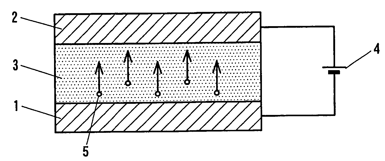
[0076]FIG. 1 is a cross-sectional view showing the schematic structure of the thermoelectric transducer according to a first embodiment of the present invention. The thermoelectric transducer of the present embodiment comprises an emitter 1, a collector 2, and an electron transport layer 3 in which a vapor phase and a solid phase coexist and which is held between the emitter 1 and the collector 2. It is preferable that the surfaces of the emitter 1 and the electron transport layer 3 are in contact, and that the surfaces of the collector 2 and the electron transport layer 3 are also in contact, as shown in FIG. 1.

[0077] In the thermoelectric transducer of the present embodiment, a voltage is applied across the emitter 1 and the collector 2 by a power source 4 in such a manner that the electric potential of the collector 2 is higher than that of the emitter 1. In the following description, although not illustrated, it is assumed that an object to be cooled is thermal...

Example

EXAMPLE 1

[0106] With regard to a method for manufacturing a thermoelectric transducer as shown in FIG. 1, the features of the present invention are further clarified with reference to a concrete Example.

[0107] First, the production procedure of an emitter 1 is explained. A polyimide sheet with a thickness of 75 μm was first baked at 2700° C. under an argon (Ar) atmosphere, producing a carbon material comprising graphite as its main composition. In this baking process, barium (Ba) was added to give the carbon material a structure that is able to easily emit electrons. Although Ba was added in this Example, the added substance is not limited to this and other metals can be used as long as they are effective in reducing work function.

[0108] Subsequently, a copper (Cu) plate was prepared for use as a collector 2, and an electron transport layer 3 having a porous structure was formed thereon. In this Example, a porous silica layer with a thickness of about 100 nm for use as the electr...

Example

EXAMPLE 2

[0112] A case where a porous silica layer which composes an electron transport layer 3 was formed by another method is explained below.

[0113] First, electrodialysis of a sodium silicate was performed to prepare a silicic-acid solution with pH 9 to pH10 (the concentration of the silica component in the solution was about 14 wt %). After adjusting the silicic-acid solution to pH 5.5, the gel material solution was applied to a sample (Cu plate) by spin coating in such a manner that its thickness became about 100 nm. A silica humid gel layer having a coated film gelled and solidified was then formed.

[0114] The Cu plate onto which the silica humid gel layer was formed was made hydrophobic by dipping it into an isopropyl alcohol solution with 5 wt % of dimethyldimethoxysilane, and decompression drying was then conducted, producing a porous silica layer composed of a dry gel. The drying conditions were a pressure of 0.05 MPa and a temperature of 50° C. The sample was allowed to...


PUM


Abstract

A thermoelectric transducer comprising an emitter (1) for emitting electrons according to the action of heat or an electric field, a collector (2) disposed so as to face the emitter (1) and collect electrons emitted from the emitter (1), and an electron transport layer (3) held between the emitter (1) and the collector (2) to serve as a region for transferring the electrons emitted from the emitter (1), the electron transport layer (3) being a porous body having a mixed structure of a vapor phase and a solid phase, the entire solid phase which composes the porous body being composed of an insulating material, and the electrons emitted from the emitter traveling in the vapor phase by applying an electric potential to the collector (2) that is higher than that applied to the emitter (1).

Description

BACKGROUND OF THE INVENTION [0001] (1) Field of the Invention [0002] The present invention relates to a solid-type thermoelectric transducer that achieves cooling operation by using thermoelectrons and field emission electrons. In particular, the present invention relates to a thermoelectric transducer comprising an electron transport layer having a porous structure in which a solid phase, composed of fine particles of an electrically non-conductive insulating material, and a vapor phase coexist, a manufacturing method thereof, a cooling device using the thermoelectric transducer, and a method for controlling the cooling device. [0003] (2) Description of the Related Art [0004] Thermoelectric transducers that achieve cooling operation by emitting electrons by using emitter materials that are able to easily emit electrons due to the action of heat or an electric field are disclosed in, for example, Journal of Applied Physics, Vol. 76, No. 7 (1994), page 4362, (hereunder referred to as...

Claims


Application Information

Patent Timeline
IPC IPC(8): H01L37/00
CPCH01L37/00F25B2321/003H10N15/00
Inventor DEGUCHI, MASAHIROTAOMOTO, AKIRAOZAKI, TOYOKAZUSHIBATA, MOTOSHI
Owner PANASONIC CORP
Why Eureka
Try Eureka