Three-dimensional-image forming device, three dimensional-image forming method and program

Active Publication Date: 2009-08-20
IGARASHI
View PDF6 Cites 17 Cited by
  • Summary
  • Abstract
  • Description
  • Claims
  • Application Information

AI Technical Summary

Benefits of technology

[0035]According to the invention, in a state of fluctuation of relative positions between the central axis of an irregular-shaped and moving tubular structure and the optical axis of the imaging means, a three-dimensional image of the tubular structure can be easily formed at high speed. By forming a three-dimensional image at high speed, at the time of endoscopic diagnosis, in addition to conventional diagnosis based on the shape data and color data, the motion of the tubular structure can be accurately examined and recorded. Further, by forming a three-dimensional image at high speed while injecting an appropriate gas or liquid into the inner space of the tubular organ, at the time of endoscopic diagnosis, the information of hardness or tension of the biologi

Problems solved by technology

In the technique shown in patent document 2, since the posture and position of the camera are always measured, and the measuring device and information processing device for the measurement are needed, and the adjustment and calculation are complicated.
Further it is impossible to measure when the subject is very close to the camera, or the subject moves rapidly or deforms repeatedly.
In the technique shown in patent document 8, a three-dimensional model is created from a pluralit

Method used


Image

  • Three-dimensional-image forming device, three dimensional-image forming method and program
  • Three-dimensional-image forming device, three dimensional-image forming method and program
  • Three-dimensional-image forming device, three dimensional-image forming method and program

Examples


Example

Embodiment 1

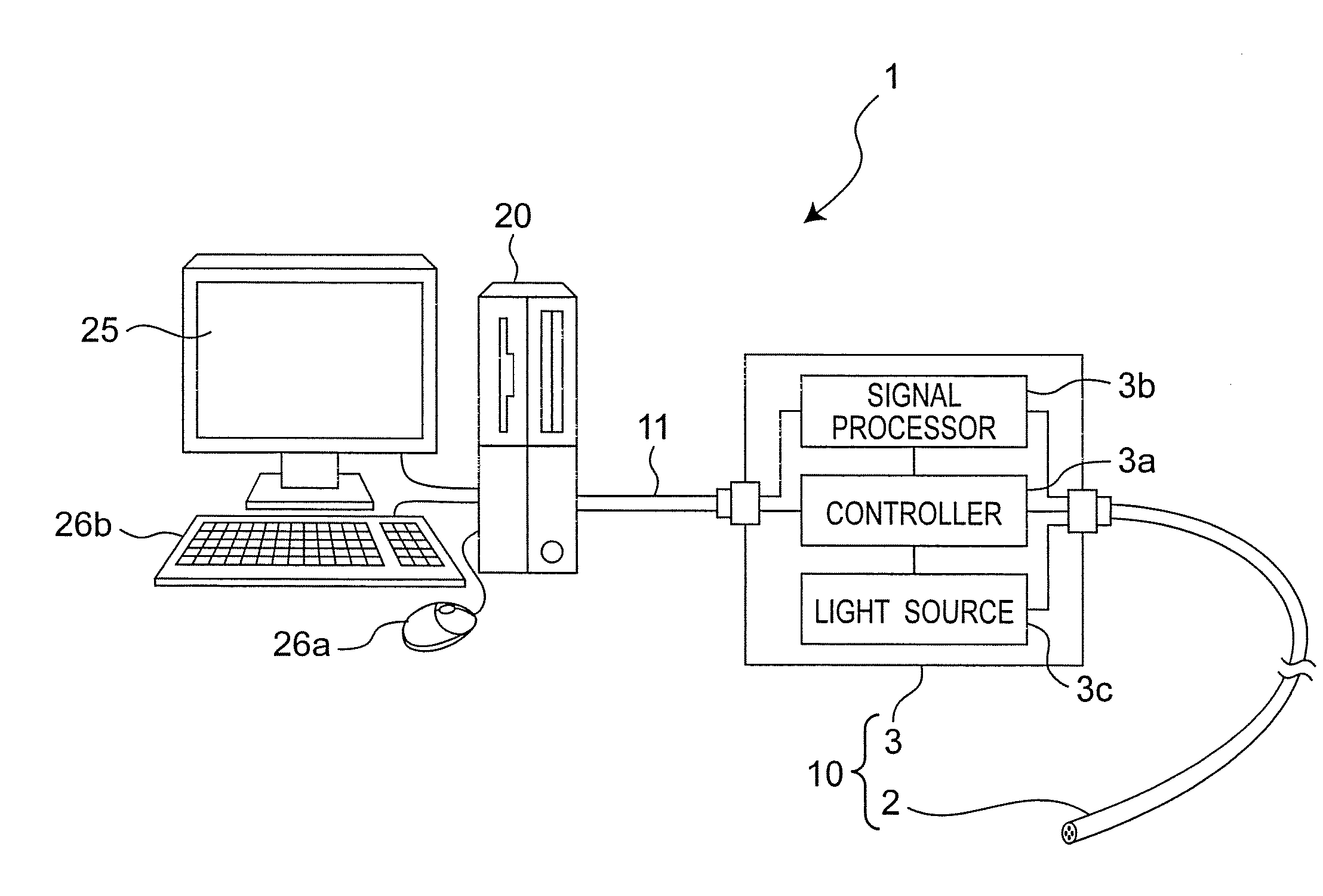
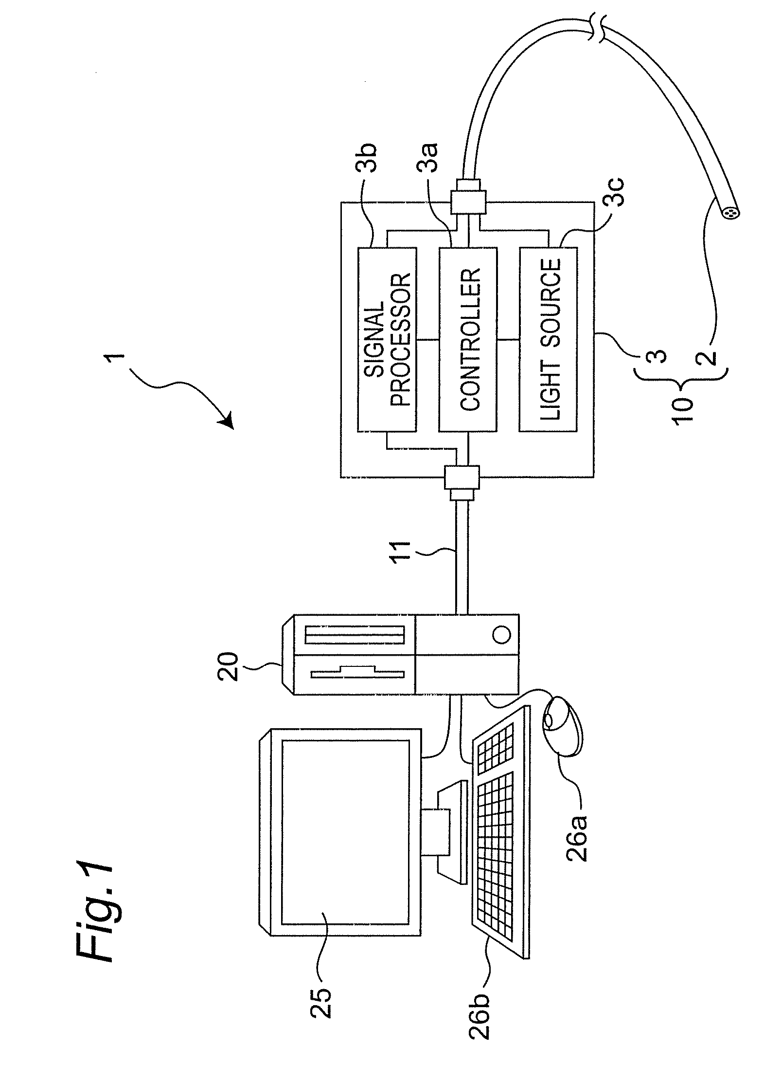
[0086]FIG. 1 is a block diagram of entire configuration of a three-dimensional image forming device in embodiment 1 of the invention. The three-dimensional image forming device 1 includes an endoscopic device 10 for taking images of inside face of tubular organ, and obtaining a video file composed of a plurality of frame images, and an information processing device 20 composed of general-purpose personal computer or the like and connected to the endoscopic device 10, for outputting display signal of the video file acquired by the endoscopic device 10 and executing a process of forming an artificial three-dimensional image based on the frame images extracted from the video file. The endoscopic device 10 and the information processing device 20 are connected by way of a cable 11 such as USB cable. The data can be transmitted between the two devices, for example, the video file acquired by the endoscopic device 10 is transmitted to the information processing device 20, or a...

Example

Embodiment 2

[0118]In this embodiment, the motion in the circumferential direction and axial direction of the endoscope 2 is detected to correct the expanded image according to the detected motion. As a result, it is possible to obtain an image reproducing more precisely the actual state of inner face of the tubular body. For this purpose, the three-dimensional image forming device of this embodiment further includes a motion detecting device for detecting the motion of the endoscope 2 in addition to the configuration of Embodiment 1.

[0119]FIG. 15 shows a configuration of the motion detecting device. The motion detecting device 50 includes an axial direction sensor 51 for detecting motion amount of the endoscope 2 in the axial direction of the endoscope 2, and a circumferential direction sensor 52 for detecting motion amount of the endoscope 2 in the circumferential direction of the endoscope 2. The sensors 51 and 52 are easily realized by using mechanism of a mouse generally used as...


PUM


Abstract

In a three-dimensional image forming device for forming a phantom three-dimensional image in accordance with an image of an inner face of a tubular structure to be observed, luminance information of pixels corresponding to a prescribed range of each frame image of the tubular structure is obtained under prescribed lighting conditions when an imaging device with an optical axis extending to an axial direction of the tubular structure moves, a relative distances in a depth direction between points and an objective lens is calculated in accordance with the luminance information, pixels corresponding to the prescribed range of each frame image in the inner face of the tubular structure is arrayed in reflection of the relative distance, and the arrayed pixels are combined for a plurality of the frame images to form a three-dimensional image of the inner face of the tubular structure.

Description

TECHNICAL FIELD[0001]The present invention relates to a three-dimensional image forming device for forming continuous three-dimensional images at high speed, on the basis of a relative distance between an objective lens and points inside a tubular structure, in which the relative distance is calculated from continuous images or video images inside the tubular structure captured by a camera or an endoscope disposed or inserted in a tubular structure such as tunnel, sewerage pipe, digestive tract or tubular organ of a patient, or the like.BACKGROUND ART[0002]Conventionally, regarding use of an endoscope device, generally, the observation region depending on the viewing field of the endoscope inserted in a tubular structure is observed grossly or displayed on a video camera, and is recorded as still image or vide image in a recoding range specified by an observer. In this case, the observed or displayed range is limited within the observation viewing field of the endoscope, and the ent...

Claims


Application Information

Patent Timeline
IPC IPC(8): H04N7/18A61B1/04G02B23/26G06T1/00
CPCA61B1/042A61B5/1076G06T7/0053G06T2207/30028G06T17/00G06T2207/10016G06T2207/10068G06T7/0065G06T7/507G06T7/55
Inventor IGARASHI, TATSUOZENBUTSU, SATOKI
Owner IGARASHI
Why Eureka
Try Eureka