Method of forming multi-piled bump

Inactive Publication Date: 2005-04-28
FUJITSU LTD
View PDF17 Cites 18 Cited by
  • Summary
  • Abstract
  • Description
  • Claims
  • Application Information

AI Technical Summary

Benefits of technology

[0014] In the method of the present invention, the metal balls can be securely piled to form the multi-piled bump. The multi-piled bump having a prescribed bump can be easily formed. By employing th

Problems solved by technology

However, width of the bumps are made greater in proportion to the diameters thereof, so separations between the bumps cannot be made narrower.
In this method, however, connecting strength between the bumps and the pads are lowered, so that the bumps cannot

Method used


Image

  • Method of forming multi-piled bump
  • Method of forming multi-piled bump
  • Method of forming multi-piled bump

Examples


Example

[0025] Preferred embodiments of the present invention will now be described in detail with reference to the accompanying drawings.

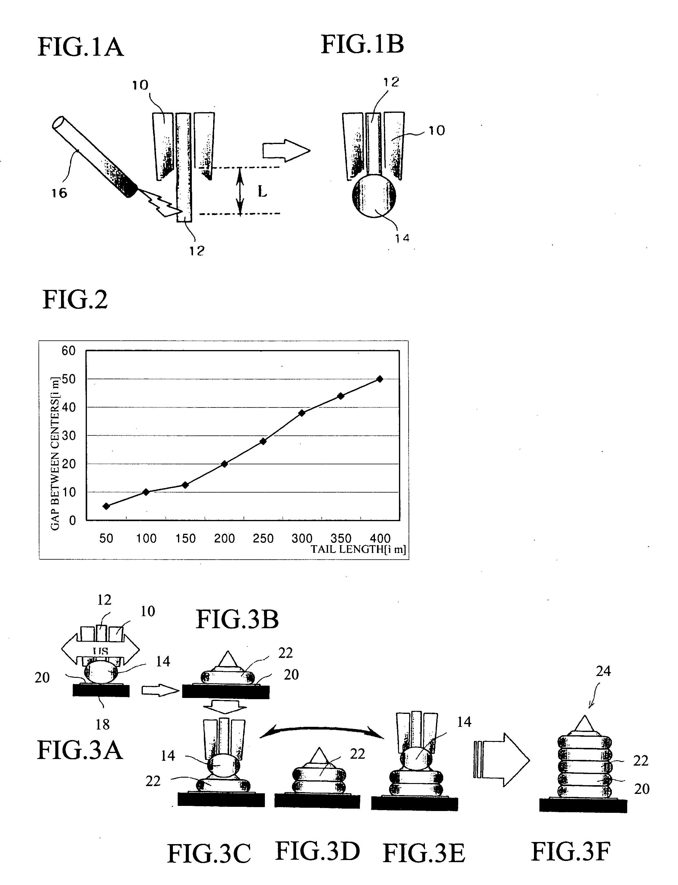
[0026]FIGS. 1A and 1B are explanation views showing a step of forming a metal ball 14, in which a front end of a metal wire 12 extended from a capillary 10 is melted to form the metal ball 14. As shown in FIG. 1A, the front end of the metal wire 12 is extended from the capillary 10. Electricity is discharged and sparked between the front end of the metal wire 12 and a discharging electrode 16, so that the front end of the metal wire is melted and formed into a spherical shape. This spherical metal is the metal ball 14 (see FIG. 1B).

[0027] When electricity is discharged and sparked between the metal wire 12 and the electrode 16, the metal wire 12 is extended outward from a front end of the capillary 10. The extended length L of the metal wire 12 is called “tail length”. Conventionally, the tail length was 150-300 i m. FIG. 2 is a graph showing a relation...


PUM


Abstract

In the method of forming a multi-piled bump, metal balls can be stably and securely piled so as to form the multi-piled bump having a prescribed height. The method of the present invention comprises the steps of: holding a metal wire by a capillary; sparking and melting the wire so as to form metal balls; piling a plurality of the metal balls with applying a load and ultrasonic vibrations thereto, and characterized in that a tail length of the metal wire, which is held by the capillary, is controlled to make a gap between a center of the metal wire and a center of the metal ball one half of a diameter of the metal wire or less.

Description

BACKGROUND OF THE INVENTION [0001] The present invention relates to a method of forming a multi-piled bump on an electrode of a semiconductor chip, etc. [0002] A semiconductor chip, which will be flip chip-connected, has stud bumps formed on aluminum pads, and the semiconductor chip is mounted, for example, on a substrate of a printed circuit board by electrically connecting the stud bumps to electrodes of the substrate. Generally, the bump is formed on the pads of the semiconductor chip by the steps of: sparking and melting a front end of a metal wire so as to form a metal ball; and pressing the metal ball onto the pad, by a capillary, with applying ultrasonic vibrations so as to connect the metal ball with the pad. [0003] Each of the bumps is formed by one metal ball, and its height is determined on the basis of a size of the metal ball formed at the front end of the metal wire, a pressing force applied to the metal ball to connect with the pad and a power of the ultrasonic vibrat...

Claims


Application Information

Patent Timeline
IPC IPC(8): H01L21/00H01L21/44H01L21/60H01L21/607H01L25/065
CPCH01L24/11H01L2924/00013H01L25/0657H01L2224/1134H01L2224/1308H01L2224/13124H01L2224/13144H01L2224/13147H01L2224/13664H01L2224/16145H01L2224/48091H01L2224/73265H01L2225/0651H01L2225/06513H01L2225/06517H01L2225/06527H01L2225/06555H01L2225/06562H01L2924/01002H01L2924/01013H01L2924/01029H01L2924/01046H01L2924/01078H01L2924/01079H01L24/73H01L2924/01005H01L2924/01006H01L2924/01033H01L2224/45147H01L2224/45124H01L2224/45144H01L2924/00014H01L2224/13099H01L2924/00H01L2224/45015H01L2224/05573H01L2224/05568H01L2924/00011H01L2224/45644H01L2224/45565H01L2924/20752H01L2224/05599H01L2224/45664
Inventor ISHIKAWA, NAOKITAKEUCHI, SHUICHIKIRA, HIDEHIKO
Owner FUJITSU LTD
Why Eureka
Try Eureka