Pneumatic tire
A technology for pneumatic tires and tires, applied in tire parts, tire treads/tread patterns, transportation and packaging, etc. Effect
- Summary
- Abstract
- Description
- Claims
- Application Information
AI Technical Summary
Problems solved by technology
Method used
Image

Examples
Embodiment 1
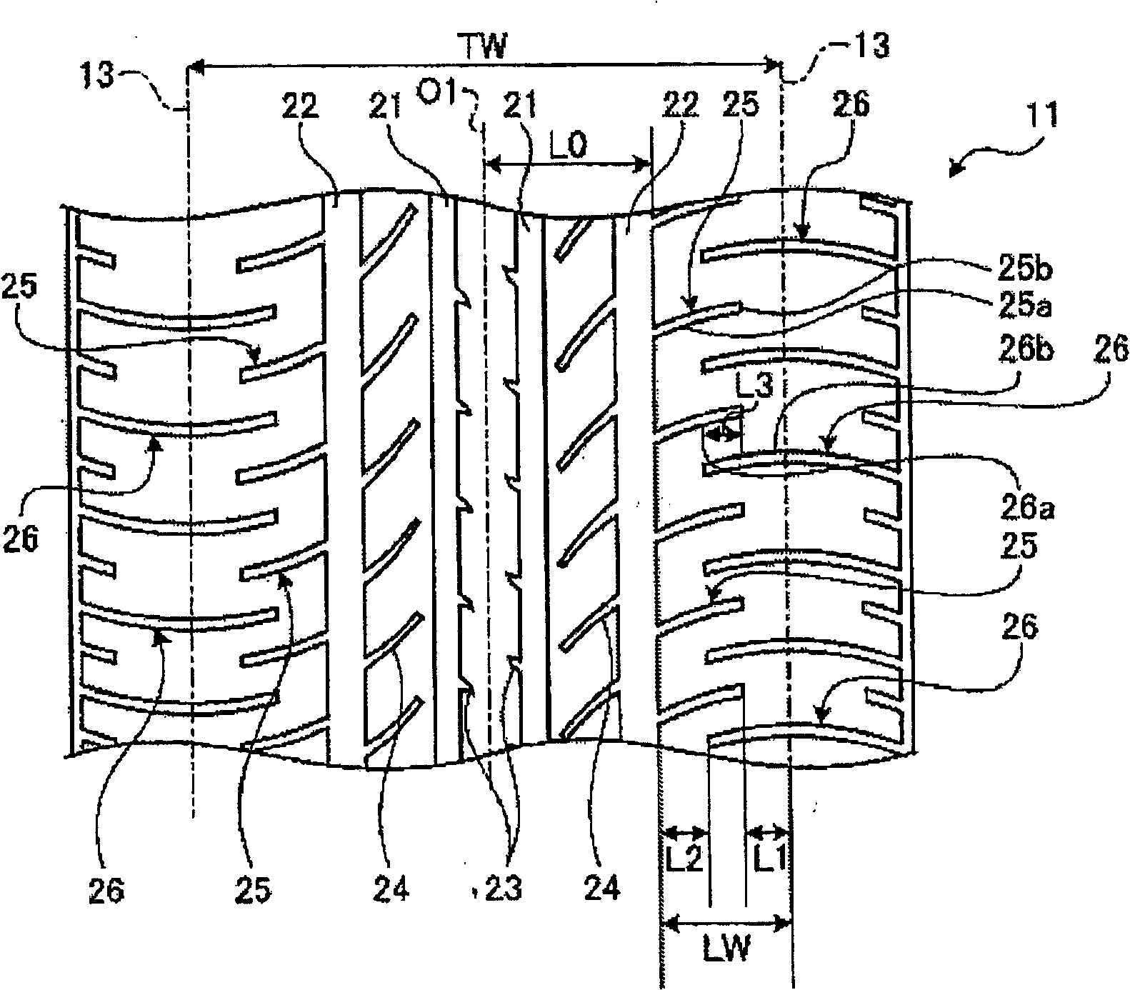
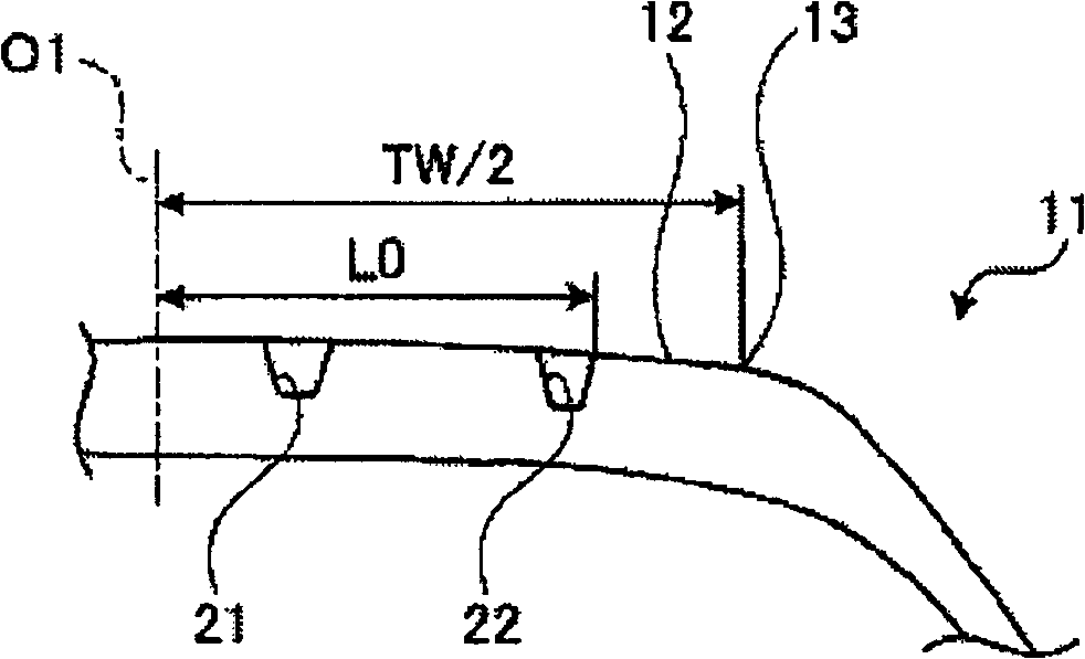
[0043] figure 1 is a plan view of a tread portion, showing a pneumatic tire according to Example 1 of the present invention; figure 2 It is a schematic sectional view showing the pneumatic tire of Example 1.
[0044] In addition, in the following description, the so-called tire width direction is a direction parallel to the rotation axis of the pneumatic tire; The outer side is the direction opposite to the direction toward the equatorial plane (equatorial line) in the tire width direction. In addition, the tire radial direction is a direction perpendicular to the rotational axis of the pneumatic tire, and the tire circumferential direction is a direction in which the pneumatic tire rotates around the rotational axis. Furthermore, the term "tire inner side" refers to the direction located inside the vehicle body when the pneumatic tire is assembled on a standard rim and mounted on the vehicle body, and the term "tire outer side" refers to the direction located outside the v...
Embodiment 2
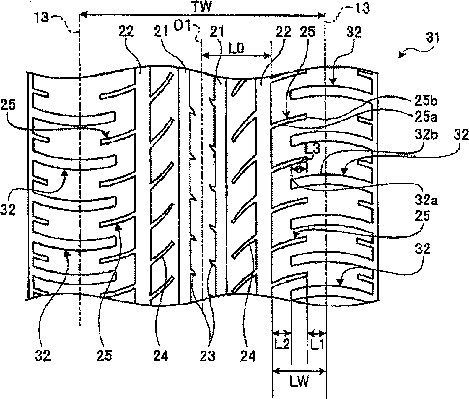
[0086] image 3 It is a plan view of a tread portion, showing a pneumatic tire according to Example 2 of the present invention. In addition, members having the same functions as those of the pneumatic tire described in the above-mentioned embodiments are denoted by the same reference numerals, and overlapping descriptions are omitted.
[0087] In Example 2, such as image 3 As shown, this pneumatic tire 31 is provided with a first main groove 21 and a second main groove 22 extending in the tire circumferential direction on both sides of the equator line O1 on the tread. Between the second main groove 22 and the tire ground contact edge 13, a plurality of first lug grooves 25 and second lug grooves 32 extending in the tire width direction are alternately provided in the tire circumferential direction. In the first pattern groove 25, one end portion 25a communicates with the second main groove 22 located on the outermost side in the tire width direction, and the other end port...
Embodiment 3
[0113] Figure 4 It is a plan view of a tread portion, showing a pneumatic tire according to Example 3 of the present invention. In addition, members having the same functions as those of the pneumatic tire described in the above-mentioned embodiments are denoted by the same reference numerals, and overlapping descriptions are omitted.
[0114] In Example 3, such as Figure 4 As shown, this pneumatic tire 41 is provided with a first main groove 21 and a second main groove 22 extending in the tire circumferential direction on both sides of the equator line O1 on the tread. Between the second main groove 22 and the tire ground contact edge 13, a plurality of first lug grooves 25 and second lug grooves 26 extending in the tire width direction are alternately provided in the tire circumferential direction. In the first pattern groove 25, one end portion 25a communicates with the second main groove 22 located on the outermost side in the tire width direction, and the other end po...
PUM
 Abstract
Description
Claims
Application Information
 - R&D
- Intellectual Property
- Life Sciences
- Materials
- Tech Scout
- Unparalleled Data Quality
- Higher Quality Content
- 60% Fewer Hallucinations
Browse by: Latest US Patents, China's latest patents, Technical Efficacy Thesaurus, Application Domain, Technology Topic, Popular Technical Reports.
© 2025 PatSnap. All rights reserved.Legal|Privacy policy|Modern Slavery Act Transparency Statement|Sitemap|About US| Contact US: help@patsnap.com