

Stop
A technology of braking device and synchronizing device, which is applied in the direction of mechanically driven clutches, clutches, mechanical equipment, etc., and can solve the problem that it cannot be guaranteed that it will not fall off in the axial direction
- Summary
- Abstract
- Description
- Claims
- Application Information
AI Technical Summary
Problems solved by technology
Method used
Image

Examples
Embodiment Construction
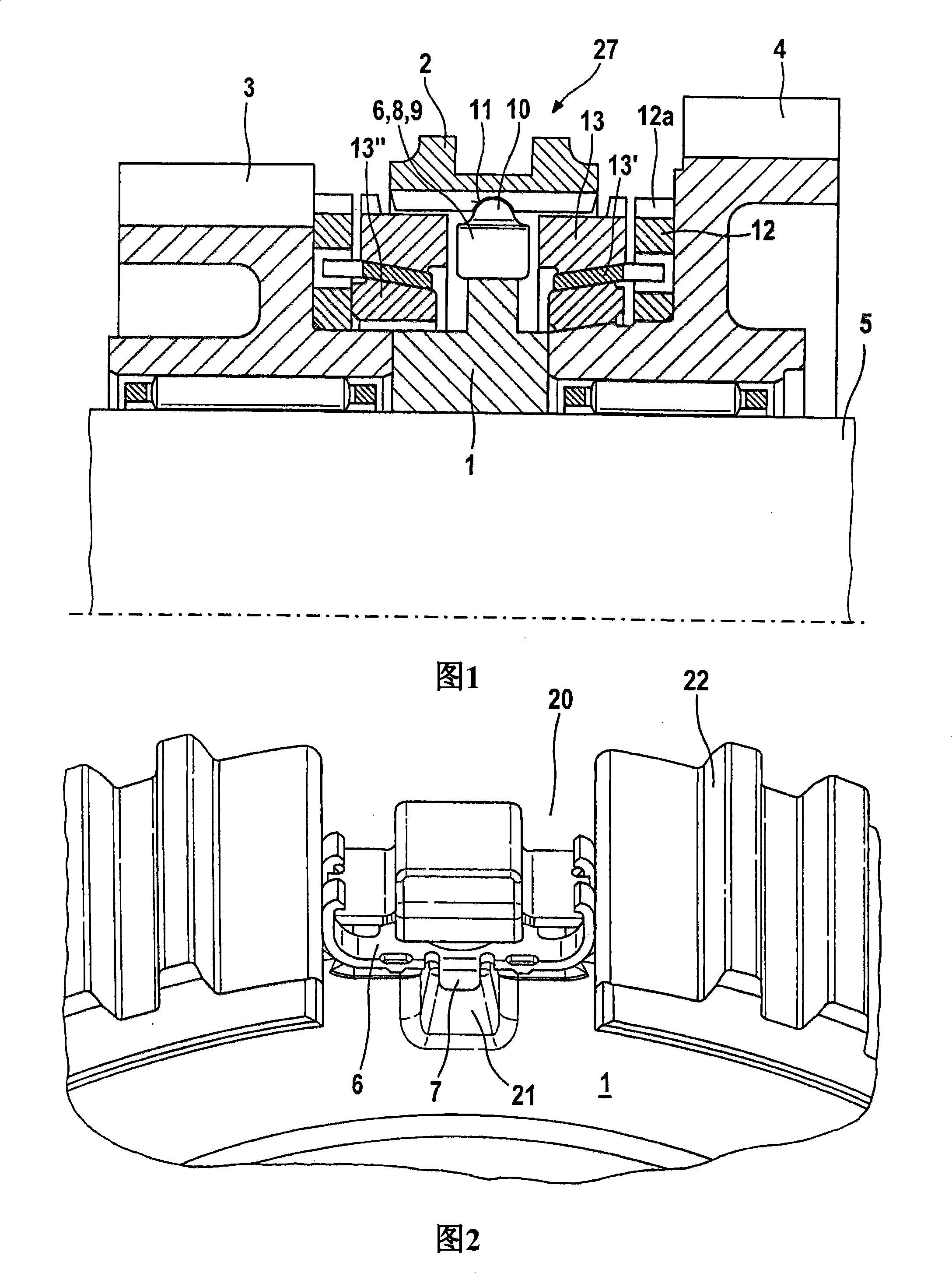
[0027] FIG. 1 shows a synchronizing device 27 with a synchronizing body 1 and a sliding sleeve 2 for selectively connecting driven wheels 3 and 4 . The driven wheels 3 and 4 are rotatable and are fixedly mounted in the longitudinal direction on the shift shaft 5 . Synchronizing body 1 is arranged in a rotationally fixed and longitudinally fixed manner on shift shaft 5 and supports sliding sleeve 2 on its periphery. The sliding sleeve 2 is arranged on the synchronizing body 1 in a rotationally fixed manner relative to the synchronizing body 1 by means of toothing and is thus selectively displaceable with respect to the shift shaft 5 toward the driven gear 3 or 4 . On each side of the synchronous body 1, a group of synchronous rings are respectively arranged between the synchronous body 1 and the driven wheels 3, 4 along the longitudinal direction.
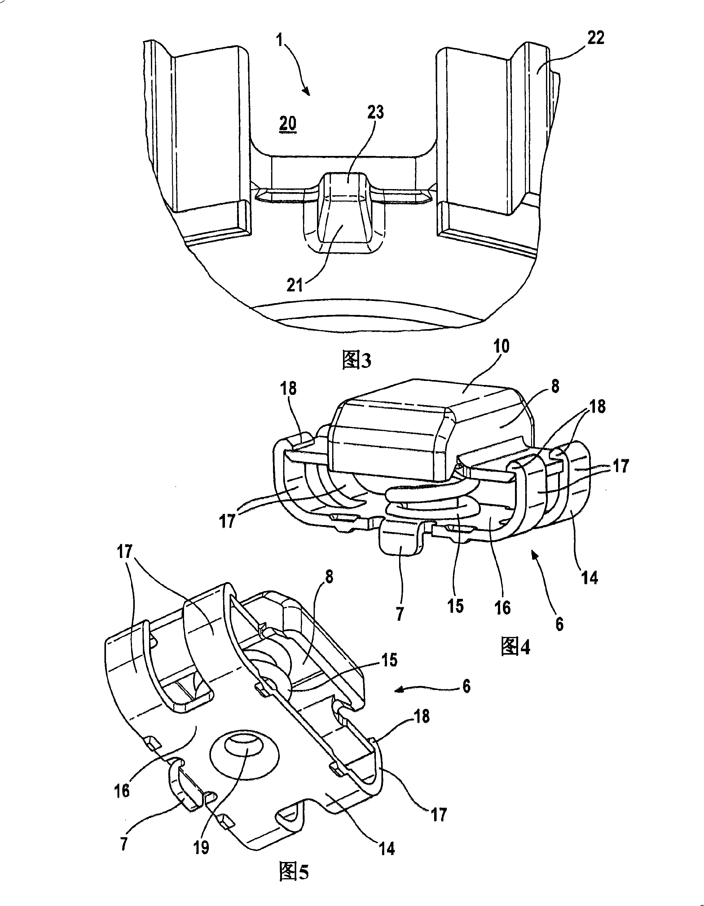
[0028] The synchronizing body 1 accommodates a plurality of braking devices 6 on its periphery, wherein the braking devices 6 are...
PUM
 Abstract
Description
Claims
Application Information