Automatic clamping fixture

A clamping and automatic technology, applied in the field of workpiece clamping devices, can solve the problems of complicated operation, inconvenience, and inability to meet the needs of large workpiece clamping, and achieve the effect of easy control and more control.

Inactive Publication Date: 2016-09-07
CHONGQING SHUANGSHI MOTORCYCLE MFG
View PDF0 Cites 7 Cited by
  • Summary
  • Abstract
  • Description
  • Claims
  • Application Information

AI Technical Summary

Problems solved by technology

[0005] The entire clamping project of this mechanism is to manually rotate the handle of the eccentric wheel, so that the eccentric wheel pushes the movable V-shaped block to clamp the workpiece, and finally needs to use positioning bolts to fix the eccentric wheel. The operation is very complicated and not convenient enough. The maximum range that can be adjusted is from the shortest radius to the longest radius of the eccentric wheel, which cannot meet the clamping requirements of large workpieces

Method used


Image

  • Automatic clamping fixture

Examples


Embodiment Construction

[0017] The present invention will be described in further detail below by means of specific embodiments:

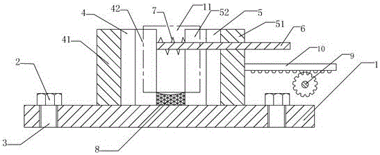
[0018] The reference signs in the drawings of the specification include: support seat 1, positioning screw 2, threaded hole 3, fixed block 4, baffle plate 41, V-shaped resisting plate 42, moving block 5, push plate 51, V-shaped pressing plate 52 , guide rod 6, spring 7, base 8, gear 9, rack 10.

[0019] The embodiment is basically as attached figure 1 Shown:

[0020] The automatic clamping fixture in this program includes a support base 1, and the left and right ends of the support base 1 are provided with threaded holes 3; the internal threads of the threaded holes 3 are connected with set screws 2; 3 A gasket is provided at the contact point, and the support base 1 is provided with a fixed block 4 and a moving block 5 in sequence from left to right, and a base 8 is provided between the fixed block 4 and the moving block 5; the fixed block 4 is composed of a baffle pl...


PUM


Abstract

The invention discloses an automatic clamping fixture, which comprises a supporting seat and a rack. Threaded holes are formed on two ends of the supporting seat; positioning screws are connected into the threaded holes; a fixed block and a movable block are sequentially arranged on the supporting seat from left to right; the fixed block is formed by a baffle plate and a V-shaped propped plate; the movable block is formed by a push plate and a V-shaped compressing plate; openings of the V-shaped propped plate and the V-shaped compressing plate are arranged oppositely; a guide rod is arranged on the V-shaped propped plate; a through hole matched with the guide rod is formed in the movable block; a gear is connected onto the rack; a rack is meshed with the gear; the free end of the rack is connected with the push plate. Compared with the prior art, according to the automatic clamping fixture provided by the invention, the gear is rotated and is meshed with the rack to drive the rack to move, so that a workpiece is clamped and loosened, the degree of automation is improved, the labor intensity of working personnel is reduced, and the labor cost is saved.

Description

technical field [0001] The invention relates to the technical field of workpiece clamping devices, in particular to an automatic clamping fixture. Background technique [0002] A milling machine refers to a machine tool that mainly uses a milling cutter to process various surfaces on a workpiece. Usually, the rotation of the milling cutter is the main movement, and the movement of the workpiece and the milling cutter is the feed movement. It can process planes and grooves, and can also process various Surfaces and gears etc. [0003] For milling machine processing, it is still necessary to fix the workpiece so that the milling cutter can perform various processing on its surface. In the prior art, there is a positioning fixture used for milling machine processing. The fixture includes a clamp body. A fixed V-shaped block, a movable V-shaped block is arranged on the clamp body in turn, and a support is provided between the fixed V-shaped block and the movable V-shaped block....

Claims


Application Information

Patent Timeline
Patent Type & Authority Applications(China)
IPC IPC(8): B23Q3/06
CPCB23Q3/06
Inventor 陈聪
Owner CHONGQING SHUANGSHI MOTORCYCLE MFG
Why Eureka
Try Eureka