Fixing apparatus

a technology of fixing apparatus and fixing plate, which is applied in the direction of electrographic process apparatus, instruments, optics, etc., can solve the problems of reducing component precision or damage, difficulty in removing recording paper, and affecting the accuracy of recording paper, so as to reduce the complication of configuration

Inactive Publication Date: 2007-08-23
SHARP KK
View PDF7 Cites 9 Cited by
  • Summary
  • Abstract
  • Description
  • Claims
  • Application Information

AI Technical Summary

Benefits of technology

[0014] The present invention was made in consideration of the problems in the related art described above, and it is an object thereof to provide a fixing apparatus in which when removing recording paper, it is possible to widely open the area around the transport path, and in which the amount of space for doing so can be reduced, thus also realizing a reduction in the size of the image forming apparatus.
[0016] With this configuration, the guide member rotates around the shaft of the roller with which the center of rotational movement of the guide member is matched, so that the guide member moves along the circumferential face of the roller. Thus, a configuration is fine as along as there is space along the circumferential face of the roller for moving the guide member, so the guide member can easily move without interfering with the surrounding components. Also, it is possible to increase the movement distance of the guide member, so that the guide member is sufficiently removed from the transport path of the recording paper and thus the area around the transport path can be widely vacated. Therefore, it is easy to remove recording paper jammed in the transport path.
[0020] With a applying energy means having this configuration, it is possible to directly open the transport path when the opening-closing door has been opened, so that the recording paper can easily be removed.
[0022] With this configuration, it is not necessary to particularly provide a rotating shaft that axially supports the guide member, and thus it is possible to suppress increasing complication of the configuration.

Problems solved by technology

Thus, when a jam occurs, in which recording paper in the midst of transport becomes blocked, it is difficult to remove the recording paper.
Several opening-closing locations are provided along the transport path so that the transport path is opened by opening these opening-closing locations, but because many components are also disposed around the transport path, even if the transport path is opened, those components may be a hindrance to removing the recording paper.
Also, there is a risk that when removing the recording paper, the recording paper will be rubbed against a peripheral component, leading to a reduction in component precision or damaging a component.
Also, the space therefore cannot be made sufficiently large, and even if the guide member 103 is rotated, it is not possible to widely vacate the area around the transport path, and thus the recording paper cannot be easily removed.
In addition, when the user makes an excessive attempt to remove the recording paper, there is a risk that the user's hand will touch the heating roller, or that the heating roller 101, the pressure roller 102, the paper separation plate 104, a temperature sensor (not shown), or the like will be damaged.

Method used


Image

  • Fixing apparatus
  • Fixing apparatus
  • Fixing apparatus

Examples


Embodiment Construction

[0036] Hereinafter, embodiments of the present invention will be described in detail with reference to the accompanying drawings.

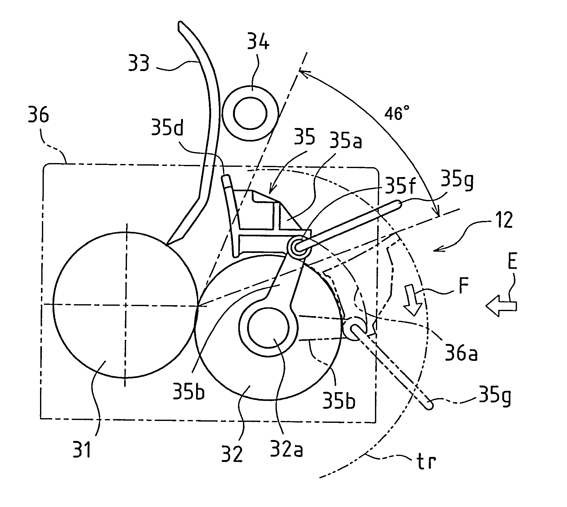
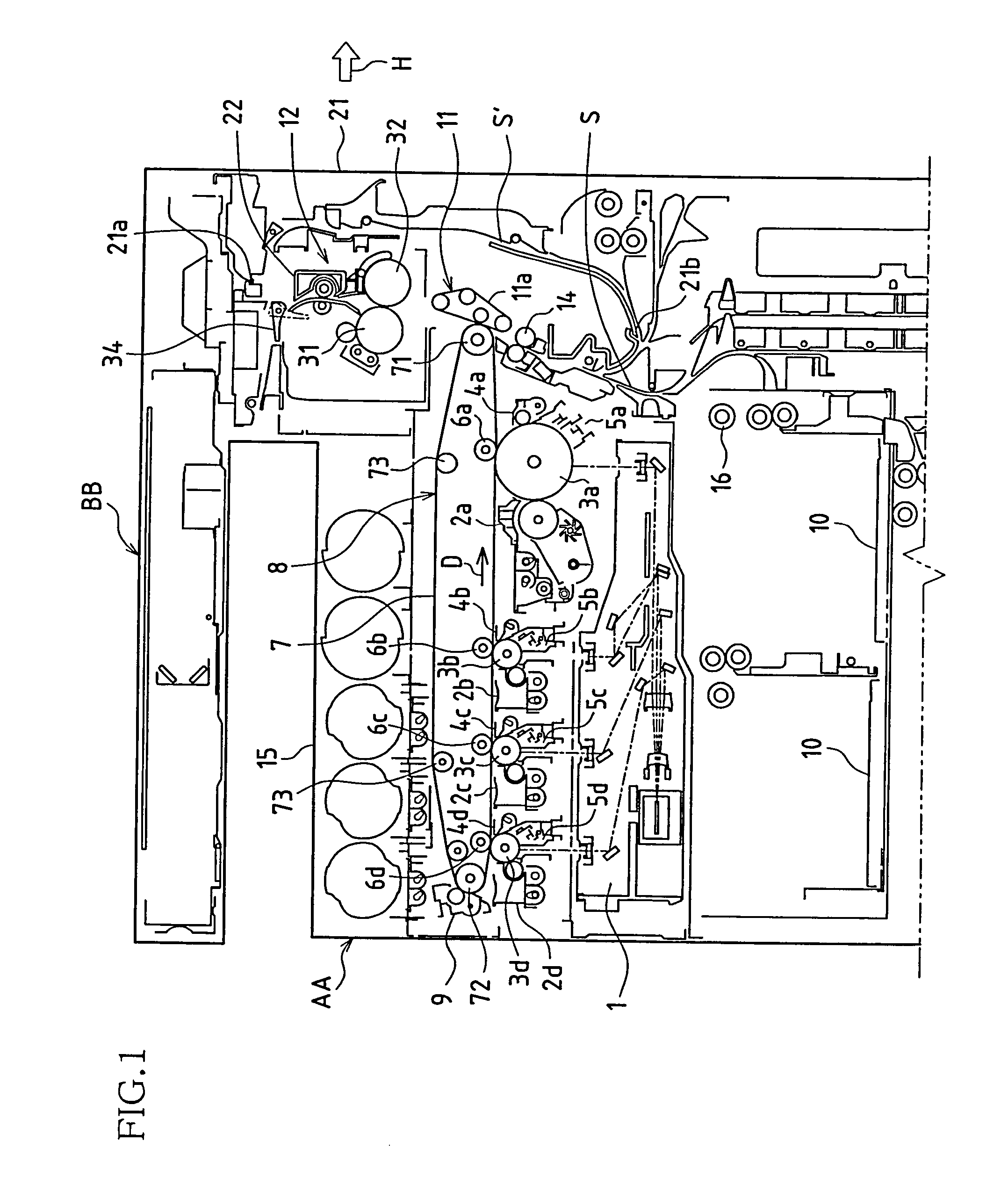
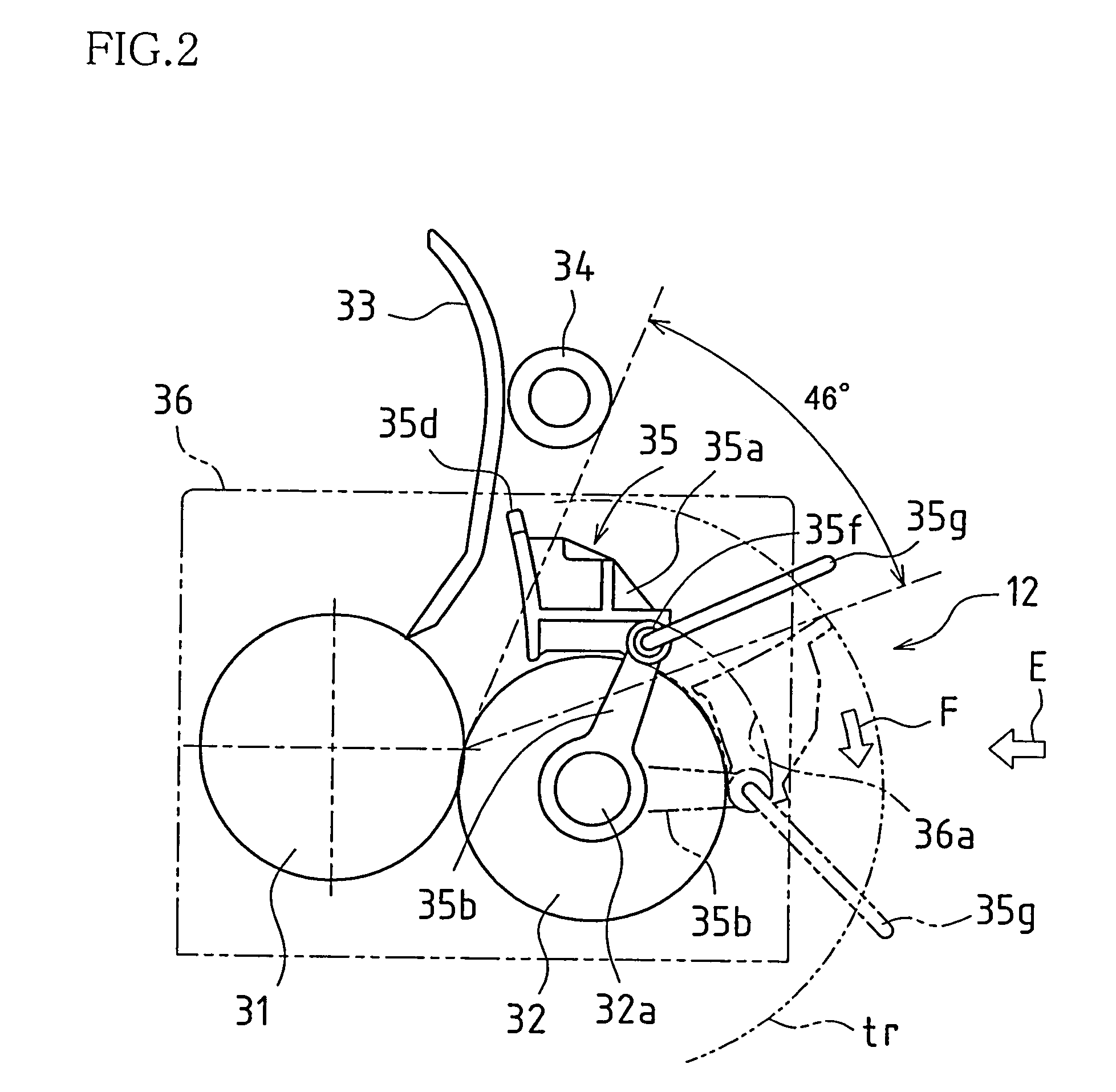
[0037]FIG. 1 is a side view showing the configuration of an image forming apparatus in which one embodiment of a fixing apparatus according to the present invention has been applied. This image forming apparatus AA forms and records on recording paper, in color or monochrome, an image of an original read from an original reading apparatus BB or an image received from outside. The image forming apparatus is configured from, for example, an exposure unit 1, a development apparatus 2, a photosensitive drum 3, a charging unit 5, a cleaning unit 4, an intermediate transfer belt unit 8, a fixing apparatus 12, a paper transport path S, a paper feed tray 10, and a discharge tray 15.

[0038] The image data handled in the image forming apparatus AA corresponds to a color image using each color black (K), cyan (C), magenta (M), and yellow (Y), or corresponds to a mon...


PUM


Abstract

In one embodiment, the fixing apparatus of the present invention is a fixing apparatus in which while recording paper is transported sandwiched between a heating roller and a pressure roller that are pressed against each other, the recording paper is guided by a guide member, and heat and pressure are applied to the recording paper to fix toner on the recording paper, the fixing apparatus configured with the guide member rotatably provided such that the guide member can be removed from the transport path of the recording paper, and the center of rotational movement of the guide member matched with a shaft of the heating roller or a shaft of the pressure roller.

Description

[0001] This application claims priority under 35 U.S.C. §119(a) on Japanese Patent Application No. 2006-045660 filed in Japan on Feb. 22, 2006, the entire contents of which are hereby incorporated by reference. BACKGROUND OF THE INVENTION [0002] 1. Field of the Invention [0003] The present invention relates to a fixing apparatus used in an electrophotographic image forming apparatus. [0004] 2. Description of the Related Art [0005] This type of image forming apparatus is provided as a copy machine, a printer, a facsimile apparatus, or the like. In this apparatus, an electrostatic latent image is formed on a photosensitive body, the electrostatic latent image on the photosensitive body is developed using toner to form a toner image on the photosensitive body, the toner image is transferred from the photosensitive body to recording paper, and heat and pressure are applied to the recording paper to fix the toner image on the recording paper. [0006] Recently, reduction in the size of tho...

Claims


Application Information

Patent Timeline
Patent Type & Authority Applications(United States)
IPC IPC(8): G03G21/00G03G15/20
CPCG03G15/2028
Inventor KUBO, TAKASHIMINAKUCHI, YASUNORIHORI, HIROAKI
Owner SHARP KK
Why Eureka
Try Eureka