Film bearing seal device

A sealing device and oil film bearing technology, applied in the direction of engine sealing, engine components, mechanical equipment, etc., can solve the problems of seal failure, poor anti-axial and radial runout effects, and few contact parts, and achieve extended use. Longevity, increased penetration resistance, and reduced maintenance costs

Active Publication Date: 2009-01-07
TIELING WUXING OIL FILM & RUBBER SEALING RES INST
View PDF0 Cites 5 Cited by
  • Summary
  • Abstract
  • Description
  • Claims
  • Application Information

AI Technical Summary

Problems solved by technology

[0012] A: When the axial distance between the inner seal ring 62 and the casing 38 is smaller than the design size, the flexible seal 10 will be deformed due to extrusion, causing the flexible protrusions 28 and 30 of the flexible seal 10 to wear and seal failure
[0013] B: When the inner diameter of the inner seal ring 62 is smaller than the design size, the inner seal ring 62 is not installed in place, that is, the tapered surface of the roll diameter is stuck, and the flexible seal 10 is squeezed and deformed, causing the flexibility of the flexible seal 10 to protrude Parts 28 and 30 are worn, and the seal fails
[0014] 2. The flexible protrusions 28 and 30 of the dynamic sealing part of this sealing device are in contact with the cylindrical shoulder surface 60, with few contact parts, the sealing surface is parallel to the axial direction of the roll, and the direction is single, resisting axial movement and radial runout poor effect

Method used


Image

  • Film bearing seal device
  • Film bearing seal device
  • Film bearing seal device

Examples


Embodiment Construction

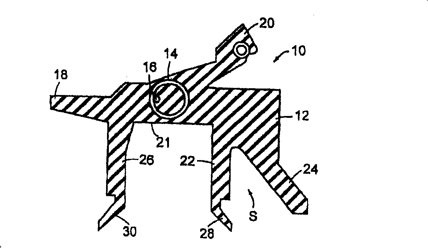
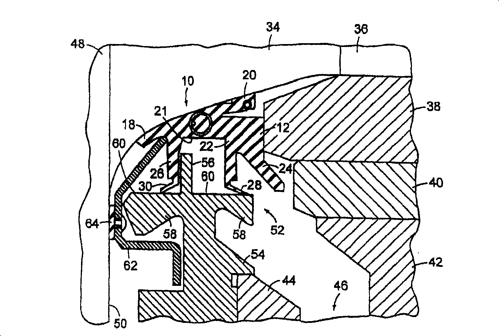
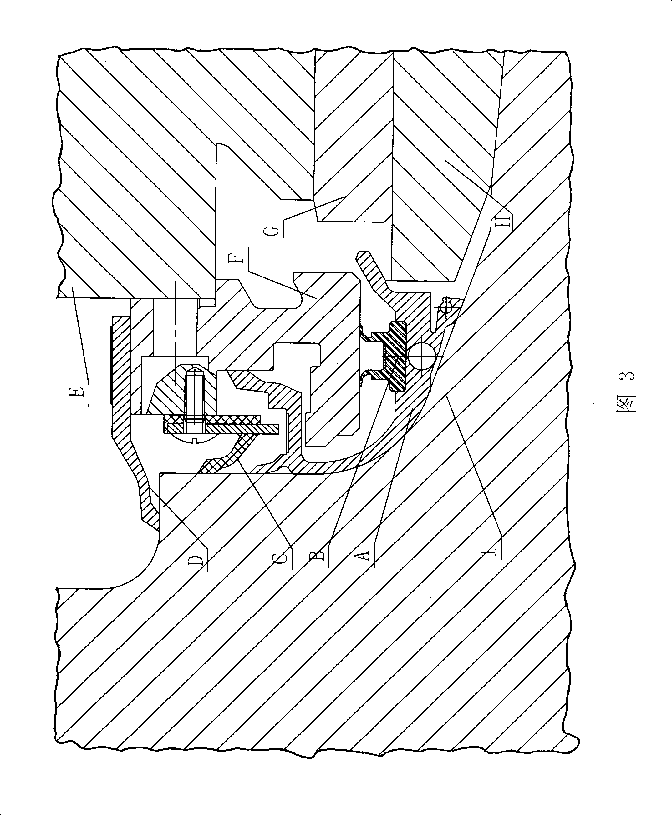
[0032] Figure 3- Figure 7 As shown, the main structure of the present invention includes a neck seal A and a rigid annular sealing end plate F fixed on the bearing seat E, and the neck seal A includes an annular seal body 1 with a slot 7 and inserted into the slot The sealing part B on 7, the coil spring 6 and the wire rope 4 are embedded in the annular sealing body 1, the slot 7 is opposite to the sealing surface 41 of the rigid annular sealing end plate, and the rigid annular sealing end opposite to the sealing surface 41 A protective water seal D is provided on the board F. The sealing part B includes a base 19 inserted into the slot 7, a water sealing limb 17 and an oil sealing limb 25 perpendicular to the base, and the water sealing limb 17 and the oil sealing limb 25 are connected with mutually diverging water sealing lips 15 And the sealing lip 23, the sealing part B inserted into the slot is placed between the rigid annular sealing end plate F and the annular sealing...


PUM


Abstract

The present invention relates to an oil film bearing sealing unit, which comprises a neck sealing part and a rigid annular sealing end plate. The essential technical points of the oil film bearing sealing unit are as follows: the neck sealing part comprises an annular sealing body with a slot, and a sealing part plugged in the slot; wherein, the sealing part is arranged between the rigid annular sealing end plate and the annular sealing body and contacted with a sealing surface; the extended part of the annular sealing body, which is on the same side as the sealing part is, is an adsorption neck; the end of the adsorption neck is connected with a secondary water-sealing lip, a water-sealing crown and a primary water-sealing lip; the secondary water-sealing lip is contacted with the concave surface of a roll neck; the primary water-sealing lip is contacted with a squeezing end surface; the extended part of the annular sealing body, which is not on the same side as the sealing part is, is a primary oil-sealing lip, is contacted with the concave surface of the roll neck; the annular sealing body is also connected with an oil-throwing lip. The axial, radial and bi-directional end surfaces of the oil film bearing sealing unit are sealed, and as a result, not only water is effectively sealed, but also friction resistance is less. The sealing part has a long service life and can be independently replaced, and therefore the maintenance cost is reduced. The adaptability to axial mounting dimension errors is improved, and the affection of axial float is also reduced during operation.

Description

technical field [0001] The invention belongs to the technical field of bearing sealing devices, and specifically relates to an oil film bearing sealing device mainly suitable for rolling mills with an axial movement of 5-10 mm and an axial circumferential dimension error of -3-5 mm. Background technique [0002] As we all know, in order to prevent lubricating oil from leaking out and prevent water from flowing into the bearing and polluting the lubricating oil of the bearing when the oil film bearing of the rolling mill is working, a sealing device is added outside the oil film bearing. The structural features of the existing common sealing devices are as follows: figure 1 , figure 2 Shown: Its main components include neck seal 10 , rigid annular seal end plate 54 and inner seal ring 62 . Wherein the neck seal 10 is molded from a flexible elastomer and has an annular seal body 12 which is internally reinforced by a coil spring 14 and a wire rope 16 embedded therein. The s...

Claims


Application Information

Patent Timeline
Patent Type & Authority Applications(China)
IPC IPC(8): F16J15/32F16J15/3232F16J15/3284
Inventor 王庚福
Owner TIELING WUXING OIL FILM & RUBBER SEALING RES INST
Why Eureka
Try Eureka