Liquid storage container and liquid filling method and liquid refilling method using the same

A liquid container and filling method technology, applied in printing and other directions, can solve problems such as inapplicability

Active Publication Date: 2009-01-14
SEIKO EPSON CORP
View PDF5 Cites 13 Cited by
  • Summary
  • Abstract
  • Description
  • Claims
  • Application Information

AI Technical Summary

Problems solved by technology

[0014] Patent Document 4 is only applicable to rack-mounted ink cartridges, not applicable to off-carriage type ink cartridges

Method used


Image

  • Liquid storage container and liquid filling method and liquid refilling method using the same
  • Liquid storage container and liquid filling method and liquid refilling method using the same
  • Liquid storage container and liquid filling method and liquid refilling method using the same

Examples


no. 1 approach

[0058] (General structure of a liquid ejecting device)

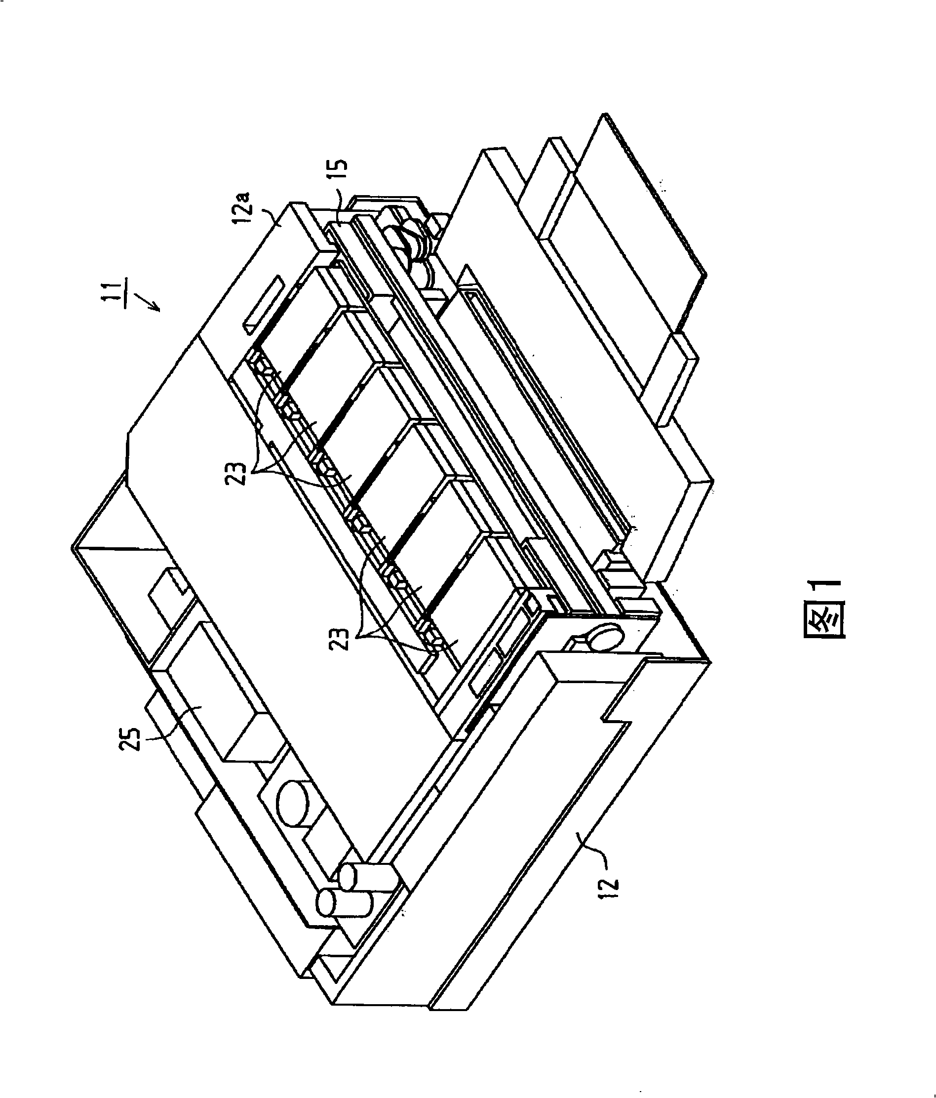
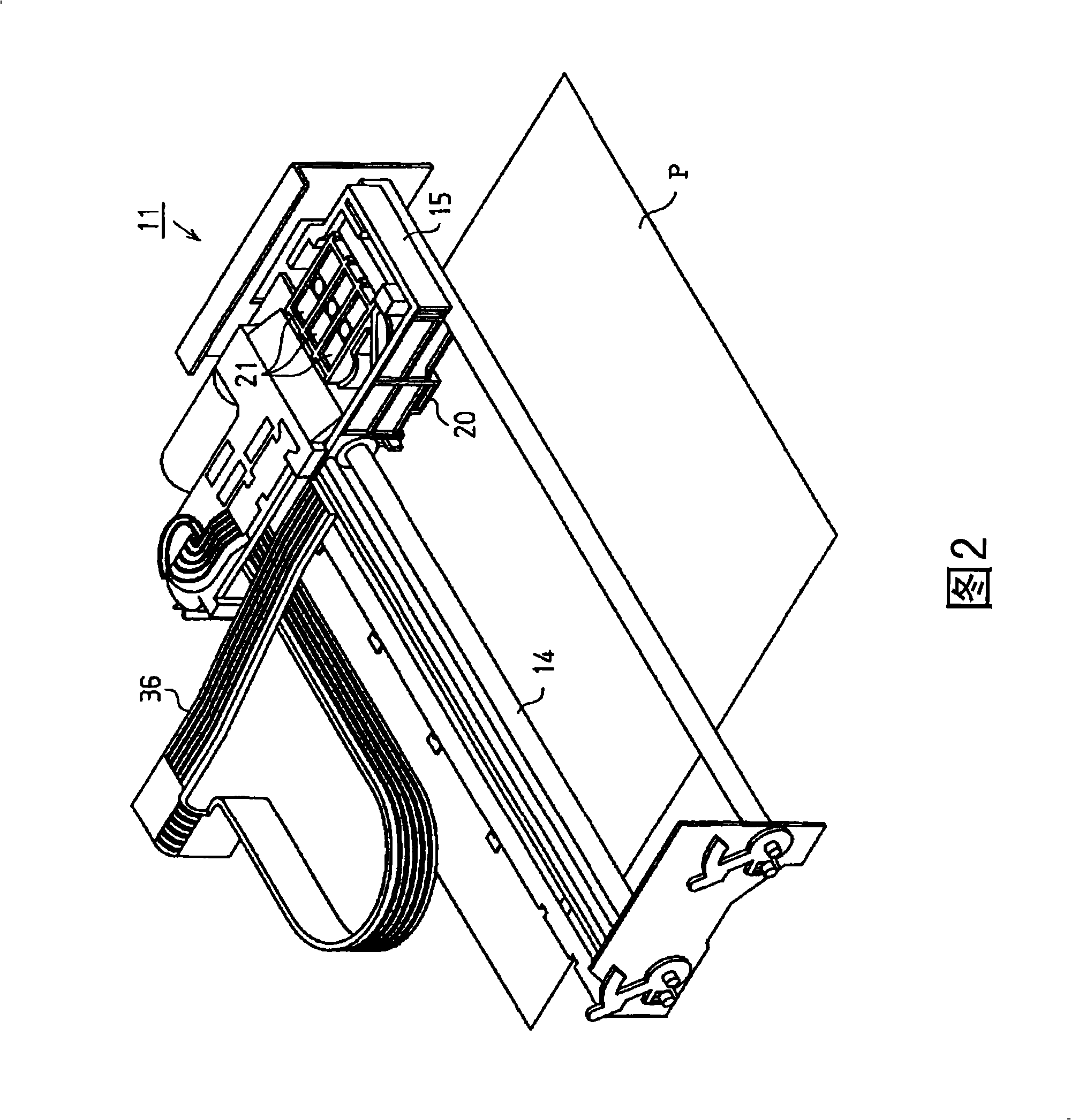
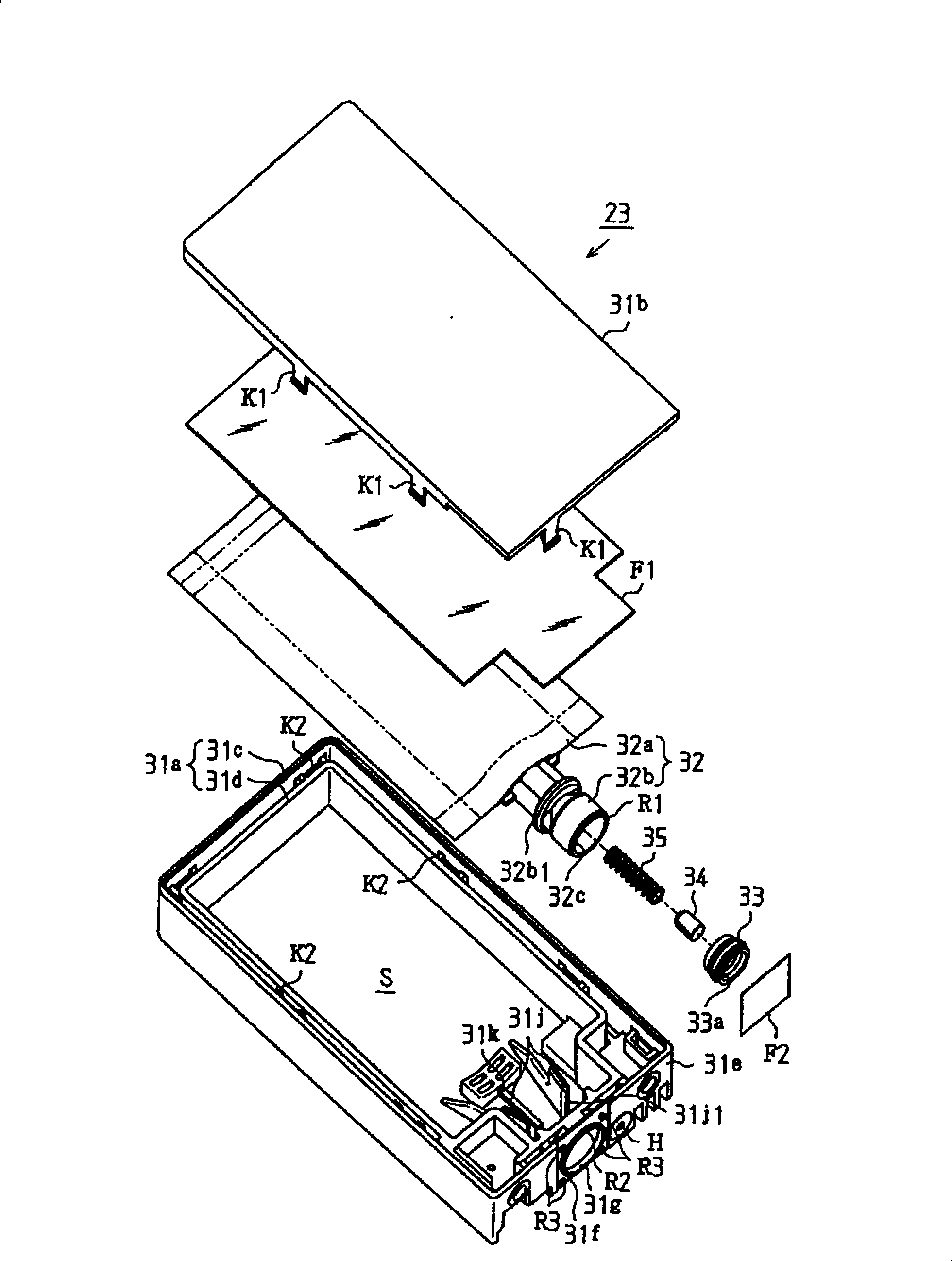
[0059] As shown in FIG. 1 , a printer 11 serving as a liquid ejecting device according to this embodiment is covered by a frame 12 . And as shown in FIG. 2, inside the frame 12 includes: a guide shaft 14, a bracket 15, a recording head 20 as a liquid ejection head, a valve unit 21, an ink cartridge 23 (refer to FIG. 1 ) as a liquid container, and a booster pump 25. (Refer to Figure 1).

[0060] As shown in FIG. 1 , the frame 12 is a box of approximately rectangular parallelepiped shape, and a box seat 12 a is formed on the front thereof.

[0061] As shown in FIG. 2 , the guide shaft 14 is formed in a rod shape, and is mounted on the frame 12 . In the present embodiment, the direction in which the guide shaft 14 extends is referred to as the main scanning direction. The bracket 15 is penetrated by the guide shaft 14 so as to be relatively movable relative to the guide shaft 14 , and can reciprocate in the main scanning...

no. 2 approach

[0138] (Structure of isolation parts)

[0139] This embodiment is based on the above-mentioned first embodiment, and the Figure 10 and Figure 11 (A), (B) shown in the isolation member 200 is replaced by Figure 14 and Figure 15 The form of the isolation member 300 shown in (A) and (B). exist Figure 14 and Figure 15 In (A) and (B), the spacer member 300 is formed of a bonding restricting member in which a plurality of holes 310 are penetratingly formed on the peripheral surface of the cylinder. In addition, if Figure 14 As shown, the insulating member 300 is also arranged below the direction of gravity in the flexible bag 107b due to its own weight.

[0140] (The role of the isolation part)

[0141] In this embodiment, if Figure 15 As shown in (A), the ink remaining in the ink pack 107 until the end is accommodated in the ink remaining space 140 formed by the spacer 300 between the two opposing flexible films 107b1, 107b2. In addition to the ink remaining space...

no. 3 approach

[0147] In this embodiment, the spacer member 200 as the sticking regulation member arranged below the gravity direction in the flexible bag 107b in the above-mentioned first embodiment is replaced with a spacer member extending on a straight line of the flow path of the ink delivery member 107a. 400 way. Therefore, except for the structure and operation of the spacer, it is the same as the first embodiment, and the description thereof will be omitted. In addition, the components having the same functions as those in the first embodiment are denoted by the same reference numerals, and descriptions thereof are omitted or simplified.

[0148] (Structure of isolation parts)

[0149] Figure 16 shows the Figure 9The shown ink lead-out member 107a is connected and arranged in the spacer member 400 of the third embodiment in the ink pack 107. FIG. Exploded stereogram. (A) to (D) of FIG. 18 show the spacer member 400 in the third embodiment. In FIG. 16, the following state is sho...


PUM


Abstract

The present invention relates to a liquid storage container and a liquid filling method thereof and a liquid refilling method using the same, and thereby the lequid which causes poor quality ro faulty operation. The liquid storage container includes a liquid containing body that is formed of a flexible film and contains liquid therein; a liquid lead-out member connected to the liquid containing body; and a spacer member disposed in the liquid containing body. The liquid containing body deforms in a direction in which inner wall surfaces of the flexible film facing each other are brought into contact with each other at the time of reduction in the remaining amount of the liquid as the inside liquid is taken out through the liquid lead-out member, and the spacer member regulates contact between parts of the inner wall surfaces of the flexible film facing each other at the time of reduction in the remaining amount of the liquid to thereby form a remaining liquid space where liquid remains.

Description

technical field [0001] The present invention relates to a liquid container, a liquid filling method using the same, and a liquid refilling method suitable for use of a liquid in which, for example, a dispersoid formed of particles such as a pigment easily settles in a dispersion medium such as a solvent . Background technique [0002] Conventionally, inkjet printers have been widely used as liquid ejecting devices that eject liquid to a target. Specifically, the inkjet printer includes a carriage, a recording head mounted on the carriage, and an ink container storing ink as liquid. When the carriage is relatively moved with respect to the recording medium, ink is supplied from the ink pack of the ink tank to the recording head, and the ink is ejected (jetted) from the nozzles of the recording head, thereby printing on the recording medium. [0003] Nowadays, with the diversification of printing, the use of pigment-dispersed inks or inks obtained by dispersing various powde...

Claims


Application Information

Patent Timeline
Patent Type & Authority Applications(China)
IPC IPC(8): B41J2/175
Inventor 野泽泉木村仁俊松本齐
Owner SEIKO EPSON CORP
Why Eureka
Try Eureka