Array magnetic-acoustic electro-conductibility imaging logging method and apparatus

An imaging logging and electrical conductivity technology, which is used in earth-moving drilling, wellbore/well components, geophysical measurement, etc.

Inactive Publication Date: 2009-01-14
INST OF ELECTRICAL ENG CHINESE ACAD OF SCI
View PDF0 Cites 23 Cited by
  • Summary
  • Abstract
  • Description
  • Claims
  • Application Information

AI Technical Summary

Problems solved by technology

For the electrical imaging logging method, in order to improve the resolution, it is necessary to arrange a large number of electrodes or coi...

Method used


Image

  • Array magnetic-acoustic electro-conductibility imaging logging method and apparatus
  • Array magnetic-acoustic electro-conductibility imaging logging method and apparatus
  • Array magnetic-acoustic electro-conductibility imaging logging method and apparatus

Examples


Embodiment Construction

[0032] The present invention will be further described below in conjunction with the accompanying drawings and specific embodiments.

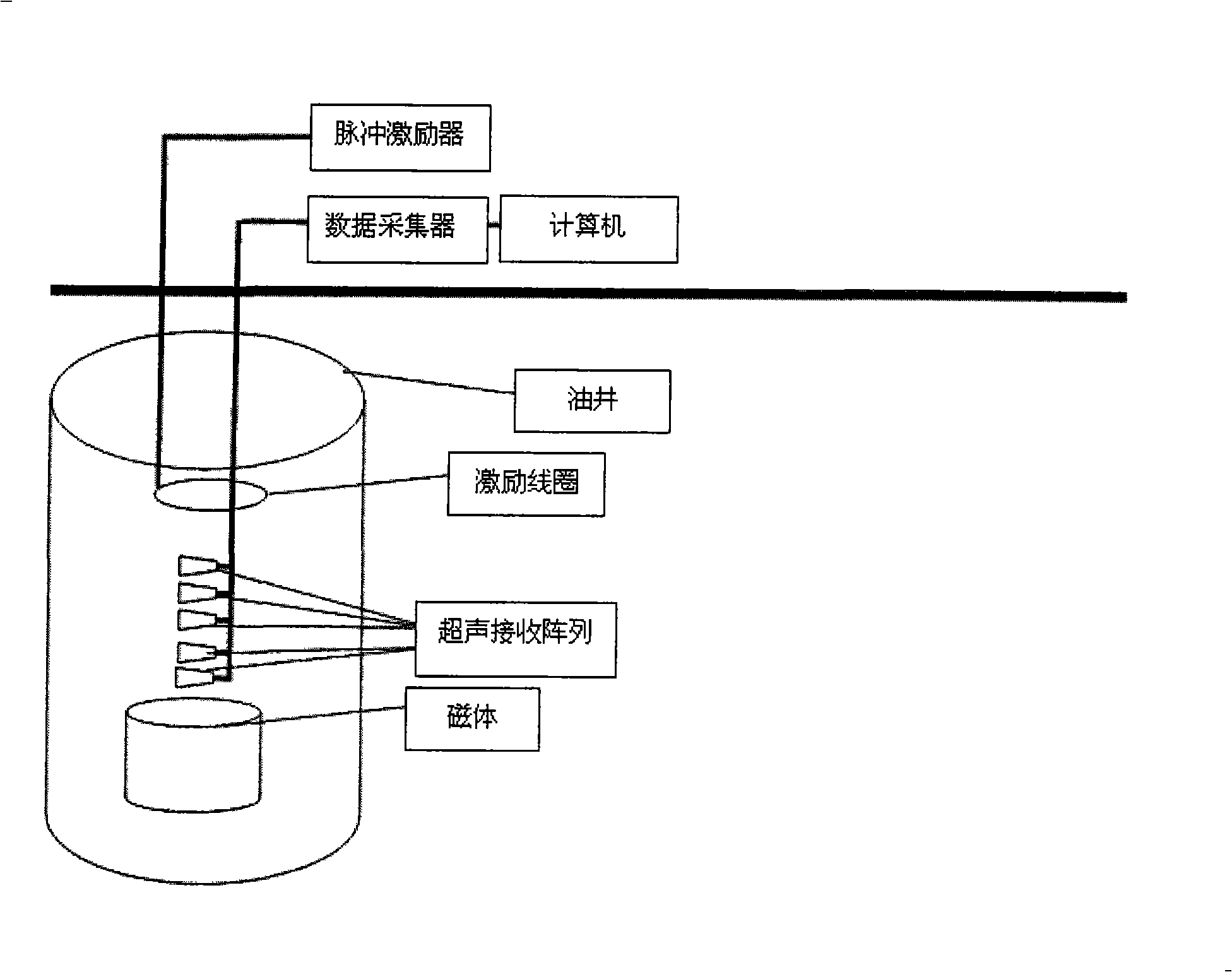
[0033] The array magneto-acoustic conductivity imaging logging method of the present invention uses magnets arranged in the well to generate a static magnetic field in the formation around the well, the pulse exciter is connected to the excitation coil, and the pulse exciter causes the excitation coil to generate a transient current to generate induction in the formation around the well The current, the induced current generates the Lorentz force under the action of the static magnetic field, thereby exciting the ultrasonic signal. The sound pressure of the ultrasonic signal transmitted through the formation to the well is measured, and the conductivity image of the formation around the well is obtained through image reconstruction.

[0034] As shown in the drawings, the array magnetoacoustic conductivity imaging logging system of the present i...


PUM


Abstract

The invention relates to an array magnetic sound electrical conductivity imaging logging method. The array magnetic sound electrical conductivity imaging logging method is characterized in that a static magnetic field is generated by magnets distributed in the well in the stratum around the well, an impulse exciter connected with an exciting coil ensures the exciting coil to generate transient current, induction current is generated in the stratum around the well, and Lorentz force is generated by the induction current under the effect of the static magnetic field, thereby exciting supersonic signals; the supersonic signals which are transmitted in the well through the stratum are received and measured, and according to the nonlinear relationship between the sound pressure and the electrical conductivity, an image of the electrical conductivity around the well is obtained through the image reconstruction. In the devices applying the array magnetic sound electrical conductivity imaging logging method, the magnets, the exciting coil and a supersonic receiving array are positioned in the oil well, and the impulse exciter, a data collector and a computer are positioned on the ground around the oil well. The supersonic receiving array is positioned between the magnets and the exciting coil, and the magnets and the exciting coil are distributed up and down. The impulse exciter is connected with the exciting coil through a cable; and the supersonic receiving array, the data collector and the computer are mutually connected sequentially.

Description

technical field [0001] The invention relates to a method and device for measuring conductivity distribution at different depths of formations around wells in the field of petroleum exploration, in particular to an array magnetoacoustic conductivity imaging logging method and device. Background technique [0002] The development of oil exploration well logging technology began in 1927 abroad and in 1939 in our country. With the development and progress of science and technology, logging instruments in my country have undergone five updates over the past 60 years, namely: semi-automatic analog logging tools, fully automatic analog logging tools, digital logging tools, numerically controlled logging tools and imaging tools. logging tool. Modern well logging is one of the technologies with the most high-tech content in the petroleum industry and occupies an important position in the petroleum industry. As the main means of information collection for oil and gas resources, the f...

Claims


Application Information

Patent Timeline
IPC IPC(8): E21B49/00G01V11/00
Inventor 刘国强夏慧江凌彤张洋李艳红李士强曾小平贺文静
Owner INST OF ELECTRICAL ENG CHINESE ACAD OF SCI
Why Eureka
Try Eureka