Light source device, image display apparatus, and monitor apparatus

一种光源装置、光选择的技术,应用在光源装置,图像显示装置及监视装置领域,能够解决具有干涉性等问题,达到减低斑点噪声、利用效率提高、自由度增高的效果

Inactive Publication Date: 2009-01-14
SEIKO EPSON CORP
View PDF1 Cites 6 Cited by
  • Summary
  • Abstract
  • Description
  • Claims
  • Application Information

AI Technical Summary

Problems solved by technology

However, although the laser light source does not have the above-mentioned problems, on the other hand, its disadvantage is that it has interference

Method used


Image

  • Light source device, image display apparatus, and monitor apparatus
  • Light source device, image display apparatus, and monitor apparatus
  • Light source device, image display apparatus, and monitor apparatus

Examples


no. 1 Embodiment approach

[0065] Next, for the first embodiment of the present invention, refer to figure 1 Be explained.

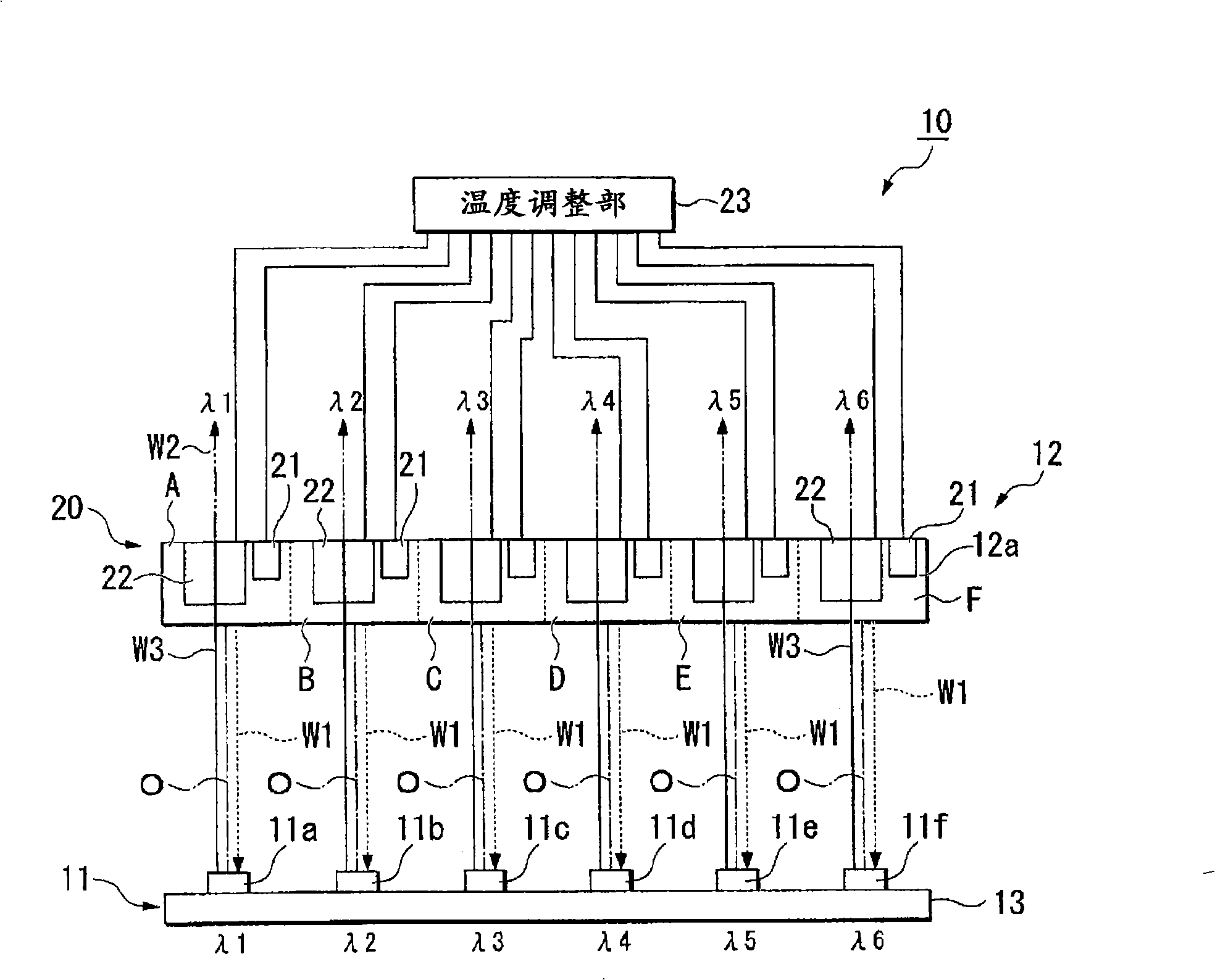
[0066] The light source device 10 according to this embodiment is, for example, figure 1 As shown, a light emitting unit 11 , a wavelength selection element 12 and a control unit 20 are provided.

[0067]The light emitting unit 11 includes six light emitting elements (semiconductor lasers, LD) 11a, 11b, 11c, 11d, 11e, and 11f that emit laser light. All of these light emitting elements 11 a to 11 f are supported by the supporting portion 13 . The peak wavelengths of light emitted from the light emitting elements 11a to 11f differ by about several nm due to manufacturing errors of the light emitting elements 11a to 11f. Here, assuming that the wavelengths of light emitted from the light emitting elements 11a-11f are λ1, λ2, λ3, λ4, λ5, λ6, then λ1>λ4>λ5>λ3>λ2>λ6. In addition, it is also possible to use a light-emitting element that emits light of a wavelength that is not acciden...

no. 2 Embodiment approach

[0107] Next, for the second embodiment of the present invention, refer to Figure 5 Be explained. In addition, in the drawings of the respective embodiments described below, the same reference numerals are attached to the parts having the same configuration as the light source device 10 according to the first embodiment described above, and description thereof will be omitted.

[0108] The light source device 40 according to this embodiment differs from the first embodiment in that it includes a light intensity adjustment unit 45 that adjusts the intensity of light emitted from the regions A to F. FIG. In other configurations, it is the same as that of the first embodiment.

[0109] Light intensity adjustment unit 45 such as Figure 5 As shown, a light intensity sensor (light intensity detection mechanism) 41 , a mirror body 42 and a light emitting element control unit 43 are provided. In addition, in this embodiment, although the same temperature adjustment unit 23 as that...

no. 3 Embodiment approach

[0120] Next, for the third embodiment of the present invention, refer to Figure 7 Be explained.

[0121] The light source device 50 according to this embodiment is, for example, Figure 7 As shown, it includes: a light emitting unit 51; a wavelength converting element 53 for converting the wavelength of light emitted from the light emitting unit 51; and a wavelength selecting element 52 for selecting and reflecting the wavelength to be converted by the wavelength converting element 53.

[0122] Also, in Figure 7 In order to simplify the drawings, the temperature adjustment unit 23 on the side of the wavelength selection element 52 is omitted for illustration.

[0123] The light emitting unit 51 includes six light emitting elements (semiconductor lasers, LD) 51a, 51b, 51c, 51d, 51e, and 51f that emit laser light. All of these light emitting elements 51 a to 51 f are supported by the supporting portion 54 . The peak wavelengths of light emitted from the light emitting elem...


PUM


Abstract

The invention provides a light source device for reducing coherence between a plurality of lasers and restraining speckle noises, an image display device and a monitoring device. The light source device includes plural light-emitting elements (11a-11f) that emit lights, a wavelength selection element (12) that has plural light selection areas in which wavelength selection is performed for the lights emitted from the plural light-emitting elements (11a-11f), respectively, and selectively reflects a part of the lights emitted from the plural light-emitting elements (11a-11f); a state detecting unit (21) that detects states of the plural light selection areas of the wavelength selection element (12), and a state changing unit (22) that changes, according to the states of the plural light selection areas (A-F) detected by the state detecting unit (21), the states of the light selection areas (A-F)of the wavelength selection element (12) to make wavelengths of the lights selected in the plural light selection areas (A-F) different from one another.

Description

technical field [0001] The present invention relates to a light source device, an image display device and a monitor device. Background technique [0002] In recent projection-type image display devices, a discharge lamp such as an ultra-high pressure mercury lamp is generally used as a light source. However, such a discharge lamp has problems such as relatively short lifetime, difficulty in instantaneous lighting, narrow range of color reproducibility, and deterioration of liquid crystal light valves by ultraviolet rays emitted from the lamp. Therefore, a projection type image display device using a laser light source for emitting monochromatic light instead of such a discharge lamp has been proposed. However, although the laser light source does not have the above-mentioned problems, on the other hand, it has the disadvantage of interference. Accordingly, since interference fringes appear as speckle noise on the projected surface on which the laser light is projected, de...

Claims


Application Information

Patent Timeline
Patent Type & Authority Applications(China)
IPC IPC(8): G03B21/20H01S5/40H01S3/23H04N7/18
CPCH04N9/3161G01J1/08H04N9/3197H01S5/4087G03B21/2013H04N9/3129H01S5/141G03B21/20H01S5/0687H01S5/4025G03B21/208G01J1/0414G01J1/0488G03B21/2033G01J1/04G01J1/0252G03B33/12H04N9/3105
Inventor 住山文香宫前章
Owner SEIKO EPSON CORP
Why Eureka
Try Eureka