Current transformer for power supply and method for manufacturing the same

A converter and power supply technology, which is applied in the manufacture of inductors/transformers/magnets, transformers, inductors, etc., can solve the problems of increasing the overall size of the converter for power supply, increasing manufacturing costs, etc.

Active Publication Date: 2009-01-14
LSIS CO LTD
View PDF0 Cites 3 Cited by
  • Summary
  • Abstract
  • Description
  • Claims
  • Application Information

AI Technical Summary

Problems solved by technology

Therefore, the required amount of the coil 40 and the number of bobbins 30 increase, thereby increasing the manufacturing cost and increasing the overall size of the power converter.

Method used


Image

  • Current transformer for power supply and method for manufacturing the same
  • Current transformer for power supply and method for manufacturing the same
  • Current transformer for power supply and method for manufacturing the same

Examples


Embodiment Construction

[0052] Reference will now be made in detail to the preferred embodiments of the invention, examples of which are illustrated in the accompanying drawings.

[0053] Hereinafter, the power converter and its manufacturing method will be described in more detail.

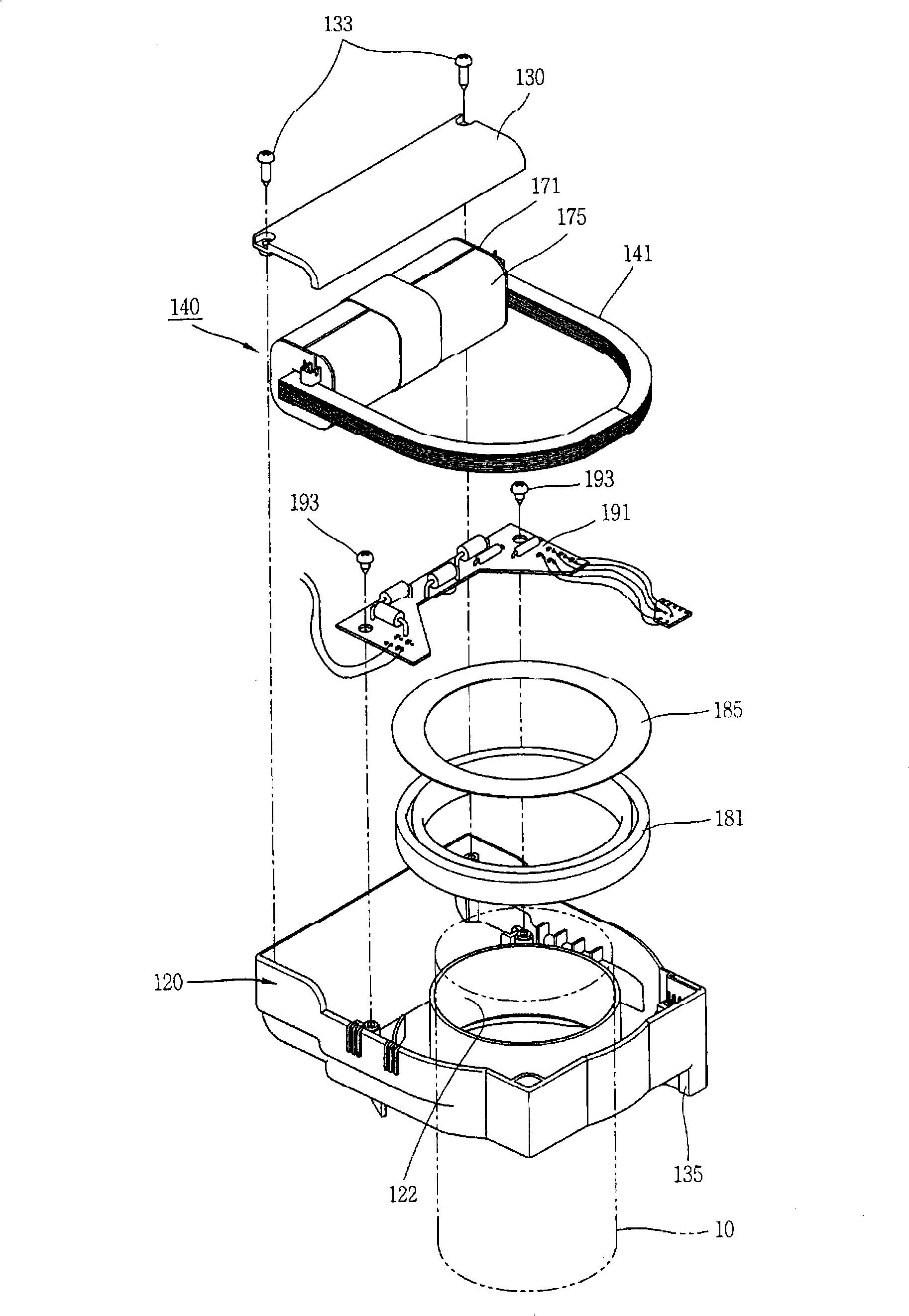
[0054] Such as Figures 3 to 5 As shown, the power converter includes: a casing 120 having an accommodation space therein; a power supply part 140 for supplying a current induced by a primary conductor 110 to a power supply object such as an overcurrent relay (OCR); a current measurement a part 181 for measuring the current flowing on the primary conductor 110; and a printed circuit board (PCB) 191 connected to the power supply part 140 and the current measuring part 181, respectively.

[0055] A primary conductor joining portion 122 for joining the primary conductor 110 is formed at the housing 120 . Also, a current measuring part 181 implemented as a circular Rogowski coil is arranged around the primary conductor ju...


PUM


Abstract

Disclosed are a current transformer for power supply, and a method for manufacturing the same. The current transformer for power supply comprises: a first core formed of a magnetic substance, and having a loop shape with a gap at one side thereof; and a supporting core formed of a magnetic substance, and disposed at one or more sides of the first core so as to block the gap. Accordingly, power supply can be smoothly performed at a small current region, and a power supply subject is prevented from being damaged at a large current region. Furthermore, the number of turns of a coil can be reduced, and an entire size of the current transformer for power supply can be made to be small.

Description

technical field [0001] The present invention relates to a power converter and a manufacturing method thereof, and more particularly, to a power converter capable of smoothly performing power supply and preventing damage to an object to be powered. Background technique [0002] Generally, a power converter is called a current transformer (CT) or a relay converter. The converter is mainly used as a power source for a current system or a power system in a power distribution device, or as a power source for a tripping coil in an air circuit breaker (ACB, air circuit breaker) or an overcurrent relay (OCR, over current relay). [0003] Such as figure 1 and 2 As shown, the power converter includes an iron core 20 having a ring shape, a bobbin 30 connected to each other so that the iron core 20 can be accommodated therein, and a coil 40 wound on the bobbin 30 . The primary conductor 10 passes through the inside of the iron core 20, and the iron core 20 is formed of an insulating ...

Claims


Application Information

Patent Timeline
Patent Type & Authority Applications(China)
IPC IPC(8): H01F38/00H01F38/28H01F41/02
CPCH01F3/14H01F38/30H01F3/12H01F38/28
Inventor 孙钟万
Owner LSIS CO LTD
Why Eureka
Try Eureka